6
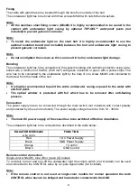
Fixing
The cable with gland has to be inserted through the hole from outside of the hull.
The underwater light has to be fixed with three screws M6x80 with nuts M6 and washers.
Note:
•
All the stainless steel fixing screws (M6x80) it is highly recommended to be sealed in the
contact with underwater light casing by optional TEF-GEL
TM
waterproof paste (not
included) to prevent galvanic corrosion.
Note:
•
To install the underwater light on the steel hull it is highly recommended to use the
optional isolation board (not included) between the hull and underwater light casing to
prevent galvanic corrosion.
Note:
•
Do not overtighten the screws as this can result in hull or underwater light damage.
Bonding
The underwater light has to be connected to the vessels bonding and cathodic protection using a pre-
tinned wire a minimum of 8 AWG (8.36 mm
2
) with green insulation or green with a yellow stripe. The
wire has to be connected to the underwater light by the help of one screw M6x80 and connected to
that screw from the inside of the hull.
Note:
•
It is highly recommended to paint the entire underwater casing exposed to the water with
anti-foul paint.
•
The optical window is protected with foil which has to be removed after anti-fouling
process.
Connection
The power supply has to be connected through the main switch (not included) with correct polarity
and protected by a fuse (not included). The power supply voltage has to be from 10 - 30Vdc.
Note:
•
The main DC power supply of the vessel has to be switched off before installation.
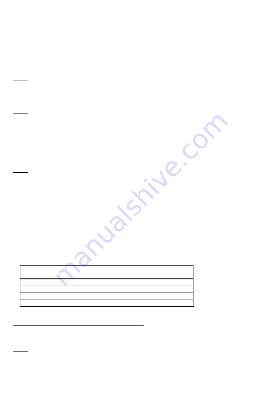
The underwater light has to be connected as described in the table below:
EQUATOR MSR36240
wire color
FUNCTION
Red
+ DC Power Supply
Black
GND Power Supply
Orange
+ Control
Brown
GND Control
Remote control connection
Single-color white (W), blue (B) or green (G) models
To remotely turn-on and turn-off the underwater light the simple switch (not included) can be used
and connected to the CONTROL wires by a 2-pole signal cable (not included).
Note:
•
If the remote control is not used at single-color models for normal operation the both
CONTROL wires have to be bridged and insulated or connected to the GND.

