Aston
®
Tire Changer ATC-5733 User’s Manual
16
www.astontechusa.com
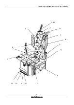
(Do not bend the hose) Then take out the part A (shown in Fig.3) from the accessory box,
unscrew the cap on the top of part A, insert the part A into the hole that go through the
main box of the machine and the bottom of the tilting arm, then tighten the bolt.
◆
The third step: Take out the part B (shown in Fig.3) from the accessory box, unscrew the
spring on one side of part B, then insert part B into the hole that go through the part D,
E, then screw the spring. Take out the side panel on the side of the machine. Connect the
PU hose (G) that go through the main box of the machine with the part F.
◆
The forth step: mount the part E on the arm (Fig.4), then mount parts D, C, B, A, G, F
in sequence. During the operation, pay attention to the PU hose and other parts.
3.4 Check the project table after installation
No.
Inspection item
Yes
No
Remarks
1
Whether the power supply voltage is consistent
with the requirements of the equipment
2
Whether the components are installed correctly
3
Whether the bolts, screws, nuts are tightened
Note:
Please fill in the inspection item list after the installation is finished.
3.5 Commissioning and debugging
3.5.1 Commissioning
◇
After the installation of the machine but before the connection with the power supply, it
is necessary to determine the user's power supply, the gas source and the requirements
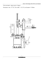
Figure 6-c

