background image

Aston

®

 Tire Changer ATC-5800 User’s Manual


35


www.astontechusa.com 


Maintenance 

5.1.1 Maintenance 


Prohibit unauthorized personnel for maintenance operation. To extend the service life of 
the tire changer, maintenance should be performed according to the requirements of the 
manual. If the machine is not maintained regularly, the operation and reliability cannot 
be guaranteed, and even cause danger to the operator or the people in the vicinity of the 
machine.  Before  any  maintenance  operation,  circuit  and  gas  supply  device  must  be 
disconnected, turn off the switch. In order to release the pressure of the air from the line, 
it is necessary to press the pedal 3-4 times. 


It must be professional staff using the original spare parts do the timely replacement of 
damaged  parts.  The  safety  device  (safety  valve,  control  valve)  of  the  unauthorized 
removal  or  replacement  is  a  violation  of  state  regulations  on  work  safety.  (Note:  the 
manufacturer is not responsible for damage caused by the parts of other manufacturer 
and the damage caused by the disassembling of the safety device). 

5.1.2 Tending 


Regular use of diesel oil to clean the turntable, to prevent the  formation of dirt. Daub 
lubricating oil in the skidway of the clamps. 


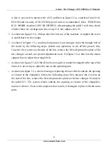
As shown in figure 15-a, control oil mist level that in the oil mist device, if the oil level 

WEAR  PROTECTIVE  CLOTHING  AND  USE  EYE  PROTECTION  WHEN  MAKING 
ANY ADJUSTMENTS OR REPAIRS TO THE MACHINE. 


BEFORE MAKING ANY INSPECTION 

ADJUSTMENT,  OR  REPAIR,  DISCONNECT  THE  POWER  SOURCE  AND  OR  AIR 
SUPPLY AND BLOCK OUT ALL MOVING PARTS TO PREVENT INJURY. 

KEEP THE  MACHINE AND THE  IMMEDIATE WORK AREA  CLEAN.  DO  NOT  USE 
COMPRESSED  AIR  TO  REMOVE  DIRT  AND  DEBRIS  FROM  THE  MACHINE. 
FOREIGN MATERIAL MAY BE PROPELLED INTO THE AIR AND INTO OPERATOR 
OR BYSTANDER CAUSING PERSONAL INJURY. 


Summary of Contents for ATC-5800

Page 1: ...Installation Operation and Maintenance User s Manual Aston Tire Changer Model ATC 5800 ASTON TECHNOLOGIES INC...

Page 2: ...Aston Tire Changer ATC 5800 User s Manual 2 www astontechusa com Semi automatic swing arm tire changer Parameters rim 10 28 Tire width 3 16 tire diameter 46 1160mm...

Page 3: ...nd Electrical Codes Carefully check the unit for correct initial function Read and follow the safety instructions Keep them readily available for machine operators Make certain all operators are prope...

Page 4: ...r damaged parts Check for condition of all moving parts breakage of parts or any condition that may affect the machines operation Do not use if any component is broken or damaged Replace or repair dam...

Page 5: ...inflation chamber or inflation cage equipped with a self gripping chuck and remote inflation gauge and valve Always inflate the tire to manufacturer s recommended cold operating pressure DO NOT OVER I...

Page 6: ...ion 11 2 1 Product introduction 11 2 2 Specifications 11 2 3 Transportation 11 2 4 Figure and part name 12 Installation and commissioning instructions 14 3 1 Installation Preparation 14 3 2 Precaution...

Page 7: ...ire Changer ATC 5800 User s Manual 7 www astontechusa com 4 3 Mounting 24 Maintenance 35 5 1 Maintenance 35 5 2 Storage and scrap 38 Fault causes and Solutions 38 Parts List Exploded Drawings 40 Warra...

Page 8: ...be operated by professional training personnel 1 3 3 Tire disassemble is forbidden to use in explosive gas 1 3 4 Before the machine is connected the user must ensure that the use of power and gas sup...

Page 9: ...to unscrew the oil cup and then add Oil mist using models for ISO Hg and viscosity for ISO vg32 oil mist special oil such as Esso Fedis k32 1405 Mobil Acauline KLUBER32 1 3 12 if the product is not us...

Page 10: ...User s Manual 10 www astontechusa com 1 4 Danger warning signs 1 5 Noise standard The noise of the tire changer shall be less than 70dB for your health and it is recommended that you place a noise me...

Page 11: ...um tire diameter 46 1160mm Maximum tire width 17 425mm Pressing force 10bar 5731 lbs 2600kg Operating air pressure 8bar 10bar 116 145psi Maximum charge pressure 3 5bar 50psi Power supply voltage 120V1...

Page 12: ...a com 2 4 Figure and part name G Wheel Clamp P column U Bead Breaker pedal I mounting dismounting head R Bead Breaker Z reversing pedal of table M Bead Breaker Pad Y turntable N horizontal pendulum ar...

Page 13: ...Aston Tire Changer ATC 5800 User s Manual 13 www astontechusa com V1 V2 Wheel Clamp Pedal C Turbo Blast Hose Assembly E hand wheel E K C P N I G Y R S Z T U V2 V1 Q M...

Page 14: ...e equipment in a safe manner The area selected should be well lit easy to clean and should be away from oil grease brake lathe chips etc Avoid areas where bystanders and customers may be present Equip...

Page 15: ...reight bill of the missing or dam aged goods Do this for your own protection 3 1 4 Unpacking Check the packaging damage and the rain and other damage phenomenon using the tool unpack the packing as sh...

Page 16: ...lation site installation site must conform to the requirements The second step unscrewing the bolts from the box the column is installed in the machine box on the specified position tighten the bolts...

Page 17: ...rules The automatic circuit breaker of 25A is required to be operated by professional personnel The power plug of the tire changer is provided with the customer The compressed air system is connected...

Page 18: ...Pull the bead breaker blade away from the machine and roll the wheel into position If servicing a performance wheel or any other wheel with Tire Pressure Sensor make sure that the valve stem is either...

Page 19: ...e on the other side of the wheel This should be the long side of the drop center It will be easier to clamp the wheel to the table top if the lower bead is loosened last Determine the mounting side of...

Page 20: ...table swing the Vertical Arm into position Use the large adjusting Knob to position the Mount Demount Head directly over the edge of the rim Push the Vertical Shaft down and position the Mount Demount...

Page 21: ...le counter clockwise NOTE THIS CLEARANCE WILL BE MAINTAINED AS LONG AS THE VERTICAL SHAFT REMAINS LOCKED THE OPERATOR MAY SWING THE ARM OUT OF THE WAY AND BACK INTO PLACE AGAIN WITHOUT NEEDING TO REPO...

Page 22: ...ally lubricate the lower bead again if there was any difficulty lubricating the lower bead earlier Put the edge of the helper disc at the bottom of lower bead lifting the bottom of tire up by turn the...

Page 23: ...ower bead is demount CUSTOM AND SPECIAL WHEELS ALLOY WHEELS IF A CUSTOM WHEEL IS DAMAGED WHILE DEMOUNTING STOP AND AVOID DAMAGING THE OTHER WHEELS CONTINUE ONLY WHEN THE CAUSE IS IDENTIFIED AND CORREC...

Page 24: ...ul attention not to pinch the tube Depress the table top pedal and rotate only a short distance at a time This allows you to stop the process should you suspect the tube is getting pinched After upper...

Page 25: ...EAD AND FOLLOWED CAREFULLY TO PREVENT ACCIDENTS AND INJURIES DURING MOUNTING CHECK TIRE AND WHEEL CAREFULLY BEFORE MOUNTING MAKE SURE THE TIRE BEAD DIAMETER AND WHEEL DIAMETER MATCH EXACTLY CONSULT TH...

Page 26: ...and rotate the wheel to begin mounting the lower bead Rotate the Table Top until the lower bead is fully mounted NEVER MOUNT A DAMAGED TIRE NEVER MOUNT A TIRE ON A RUSTY OR DAMAGED WHEEL DAMAGED TIRE...

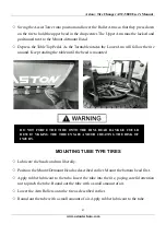
Page 27: ...e table until the bead is mounted MOUNTING TUBE TYPE TIRES Lubricate the beads and rim liberally Position the Mount Demount Head as described earlier Mount the bottom bead first Apply rubber lubricant...

Page 28: ...G MAINTENANCE SECTION OF THIS MANUAL FOR INSTRUCTIONS IF THE RIM HAS BEEN CLAMPED FROM THE OUTSIDE FOR TIRE MOUNT ING RELEASE THE CLAMPS ONCE BEAD SEAL IS OBTAINED LIFT THE TIRE AND MOVE THE CLAMPS TO...

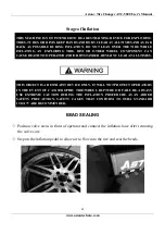
Page 29: ...sition Tire Inflation The unit is equipped with a Pressure Limiter Regulator to assist the operator with proper tire inflation The Pressure Limiter will keep most car and light truck tires from inflat...

Page 30: ...G TIRES TUBES OR RIMS KEEP HANDS AND BODY CLEAR AT ALL TIMES AND AS FAR BACK AS POSSIBLE DURING INFLATION DO NOT LEAN OVER THE TIRE WHILE INFLATING AN EXPLODING TIRE RIM OR OTHER WHEEL COMPONENT CAN C...

Page 31: ...flation pedal and open the Turbo Blast Valve for less than one full second The blast of air from the Turbo Blat Nozzle will expand tire and seal the beads NEVER POINT NOZZLE TOWARDS YOURSELF OR OTHER...

Page 32: ...ssure Most European import cars and many aftermarket alloy wheels are very tight and can be difficult to bead seat Also note that asymmetrical hump and run flat tires are extremely difficult to bead s...

Page 33: ...ENTIRE BODY AWAY FROM INFLATING TIRE AN EXPLODING TIRE WHEEL OR BEAD SEALING EQUIPMENT MAY PROPEL UPWARD AND OUTWARD WITH SUFFICIENT FORCE TO CAUSE SERIOUS INJURY OR DEATH TO OPERATOR OR BYSTANDER NE...

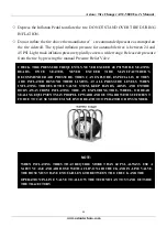
Page 34: ...HAN 60 PSI ALWAYS USE A SAFETY CAGE AND AIR HOSE WITH A CLIP ON AIR CHUCK AND IN LINE VALVE THE HOSE MUST HAVE ENOUGH LENGTH BETWEEN THE CHUCK AND THE OPERATION IN LINE VALVE TO ALLOW THE TECHNICIAN T...

Page 35: ...afety valve control valve of the unauthorized removal or replacement is a violation of state regulations on work safety Note the manufacturer is not responsible for damage caused by the parts of other...

Page 36: ...eration to cut off the power first Unscrew the 4 screws on the side of the box remove the left side protective plate of the tire changer second use special adjustment screw X Figure 15 c that is in th...

Page 37: ...Aston Tire Changer ATC 5800 User s Manual 37 www astontechusa com Figure 15 b Figure 15 a Figure 15 c Figure 15 d Figure 15 e...

Page 38: ...r to provide help We will be the first time to help you to solve the failure Provide the relevant fault information and fault pictures thus the manufacturer can get rid of the trouble at the fastest s...

Page 39: ...e adjustment is not correct or faulty Adjust or replace the locking plate Figure 18 d Working head screw loose Tighten screws Figure 12 a The pedal is not located at work position Return spring has tr...

Page 40: ...Changer ATC 5800 User s Manual 40 www astontechusa com Parts List and Exploded Drawings 580A100 Box Unit Weldment 1 580A200 Tower Unit Weldment 2 5803000 Swing Arm ASSY 3 730 Turntable ASSY 4 380 Bod...

Page 41: ...hose parts returned to the factory freight prepaid which prove upon inspection to be defective Aston will pay labor costs for the first 12 months only on parts returned as previously described These w...

Reviews:

Related manuals for ATC-5800