background image


www.astontechusa.com 

9


Aston Tire Changer ATC-8823 User’s Manual   

1.3.9 Manufacturers are responsible for the damage caused by the use of other parts of the 
manufacturer or the damage of the safety device. 

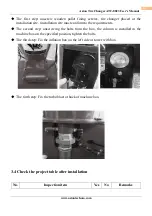
1.3.10 periodically check the oil mist, oil, if the oil level is low and need to unscrew the oil 
cup and then add. Oil mist using models for ISO Hg and viscosity for ISO vg32 oil mist 
special oil (such as: Esso Fedis k32, 1405, Mobil Vacouline, KLUBER32) 

1.3.11 if the product is not used for a long time, please user A. disconnect all power supply, 
B. and lubricate the turntable fixture slide to prevent oxidation. 

1.3.12 when deciding to scrap equipment, to determine the total energy of all the energy to 
be cut off, according to the relevant laws and regulations for all non-ferrous metals and non-
ferrous metal scrap processing. 
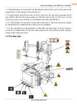
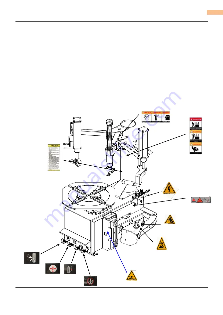
1.4 Warning signs 


Summary of Contents for ATC-8823

Page 1: ...www astontechusa com 1 Aston Tire Changer ATC 8823 User s Manual Installation Operation and Maintenance User s Manual Aston Tire Changer Model ATC 8823 ASTON TECHNOLOGIES INC...

Page 2: ...safety instructions Keep them readily available for machine operators Make certain all operators are properly trained know how to safely and correctly operate the unit and are properly supervised All...

Page 3: ...cted from the job at hand Check for damaged parts Check for condition of all moving parts breakage of parts or any condition that may affect the machines operation Do not use if any component is broke...

Page 4: ...ating the tire when demounting or mounting to avoid damage to the tire beads Always follow all applicable Local State and Federal Codes Rules and Regulations such as the Federal OSHA Standard Number 1...

Page 5: ...rer s recommended maximum inflation pressure Failure to follow these instructions may cause the tire and rim to separate with tremendous force resulting in serious personal injury or death Semi automa...

Page 6: ...1 Product introduction 10 2 2 Specifications 10 2 3 Transportation 11 2 4 Figure and part name 11 Installation and commissioning instructions 14 3 1 Installation Preparation 14 3 2 Precautions during...

Page 7: ...ww astontechusa com 7 Aston Tire Changer ATC 8823 User s Manual Maintenance 35 5 1 Maintenance 35 5 2 Storage and scrap 38 Fault causes and Solutions 38 Parts List and Exploded Drawings 40 Warranty 42...

Page 8: ...raining personnel 1 3 3 Tire disassemble is forbidden to use in explosive gas 1 3 4 Before the machine is connected the user must ensure that the use of power and gas supply and mechanical requirement...

Page 9: ...mist using models for ISO Hg and viscosity for ISO vg32 oil mist special oil such as Esso Fedis k32 1405 Mobil Vacouline KLUBER32 1 3 11 if the product is not used for a long time please user A discon...

Page 10: ...nt and quick disassemble and installation of wheel size of 10 to 28 the tire width of 14 26 and the diameter of the tire is 1160mm 2 2 Specifications Special points Specifications Outer rim 12 24 Inne...

Page 11: ...lifting device such as a forklift or pallet jack Only personnel who are experienced and qualified on material handling procedures should handle any transportation or moving of machine 2 4 Figure and p...

Page 12: ...echusa com 12 Aston Tire Changer ATC 8823 User s Manual Y Turntable N Horizontal Pendulum arm K Locking Handle Q Oil Drier V1 Wheel Clamp Pedal C Turbo Blast Hose Assembly E Hand Wheel M Vertical Reve...

Page 13: ...www astontechusa com 13 Aston Tire Changer ATC 8823 User s Manual E K C P N I G Y R Q Z U V2 V1 M V3...

Page 14: ...e manner The area selected should be well lit easy to clean and should be away from oil grease brake lathe chips etc Avoid areas where bystanders and customers may be present Equipment installation lo...

Page 15: ...your own protection 3 1 4 Unpacking Check the packaging damage and the rain and other damage phenomenon using the tool unpack the packing as shown in Picture please dispose of packaging box lest the...

Page 16: ...must conform to the requirements The second step unscrewing the bolts from the box the column is installed in the machine box on the specified position tighten the bolts The third step Fix the inflati...

Page 17: ...5A is required to be operated by professional personnel The power plug of the tire changer is provided with the customer The compressed air system is connected to the machine by a pipe joint on the ri...

Page 18: ...positioning a tire for bead loosening Pull the bead breaker blade away from the machine and roll the wheel into position If servicing a performance wheel or any other wheel with Tire Pressure Sensor m...

Page 19: ...around and repeat procedure on the other side of the wheel This should be the long side of the drop center It will be easier to clamp the wheel to the table top if the lower bead is loosened last Det...

Page 20: ...e top After the wheel is secured to the Turntable swing the Vertical Arm into position Use the large adjusting Knob to position the Mount Demount Head directly over the edge of the rim Push the Vertic...

Page 21: ...the Bead Lifting Tool down and away from the wheel to lower the bead into the Drop Center while lifting up on the Table Top Pedal to rotate the turntable counter clockwise NOTE THIS CLEARANCE WILL BE...

Page 22: ...lty lubricating the lower bead earlier Insert the smooth curved end of the Bead Lifting Tool over the tab end of Mount Demount Head and below the lower bead of the tire Push the Bead Lifting Tool down...

Page 23: ...SPECIAL WHEELS ALLOY WHEELS IF A CUSTOM WHEEL IS DAMAGED WHILE DEMOUNTING STOP AND AVOID DAMAGING THE OTHER WHEELS CONTINUE ONLY WHEN THE CAUSE IS IDENTIFIED AND CORRECTED Some manufacturers offer whe...

Page 24: ...e top pedal and rotate only a short distance at a time This allows you to stop the process should you suspect the tube is getting pinched After upper bead is demount remove tube and demount lower bead...

Page 25: ...BEFORE MOUNTING MAKE SURE THE TIRE BEAD DIAMETER AND WHEEL DIAMETER MATCH EXACTLY CONSULT THE RUBBER MANUFACTURER S ASSOCIATION FOR APPROVED RIM WIDTHS FOR TIRE SIZES ATTEMPTS TO FORCE A BEAD SEAT ON...

Page 26: ...Assist Tower into position and lower the Roller Arms so that they press down on the tire to hold the upper bead in the drop center The Upper Arm must be locked and positioned next to the Mount demoun...

Page 27: ...ate only a short distance at a time Mount the top bead INFLATION Review the following descriptions and diagrams carefully Refer to them as necessary during wheel restraint bead sealing bead seating an...

Page 28: ...ve and into the tire for inflation Tire pressure is not indicated on the gauge in this position THE CLIP ON AIR CHUCK ON THE END OF THE INFLATION HOSE AND ALL INFLATION RELATED COMPONENTS SHOULD BE CH...

Page 29: ...Inflation CHECK THE FUNCTION OF THE PRESSURE LIMITER REGULARLY MAINTAIN IT ACCORDING TO THE INSTRUCTIONS PROVIDED IN THIS MANUAL FOR SAFE AND PROPER OPERATION DO NOT TAMPER WITH OR ATTEMPT TO ADJUST...

Page 30: ...ve core Step on the inflation pedal to allow air to flow into the tire and seal the beads THIS OBJECT IS A RESTRAINT DEVICE ONLY IT WILL NOT PROTECT OPERATORS IN THE EVENT OF CATASTROPHIC TIRE WHEEL R...

Page 31: ...Nozzle to the direct air towards the Rim Center just under the Rim Lip NEVER POINT NOZZLE TOWARDS YOURSELF OR OTHER PERSONS INSPECT NOZZLE TIRE AND WHEEL FOR DEBRIS NOZZLE MUST BE POINTED TOWARD TIRE...

Page 32: ...40 PSI is the maximum safe pressure at this stage regardless of tire operating pressure Most European import cars and many aftermarket alloy wheels are very tight and can be difficult to bead seat Al...

Page 33: ...G THROUGH THE VALVE STEM KEEP HANDS ARMS AND ENTIRE BODY AWAY FROM INFLATING TIRE AN EXPLODING TIRE WHEEL OR BEAD SEALING EQUIPMENT MAY PROPEL UPWARD AND OUTWARD WITH SUFFICIENT FORCE TO CAUSE SERIOUS...

Page 34: ...KEEP HANDS ARMS AND ENTIRE BODY AWAY FROM INFLATING TIRE AN EXPLODING TIRE WHEEL OR BEAD SEALING EQUIPMENT MAY PROPEL UPWARD AND OUTWARD WITH SUFFICIENT FORCE TO CAUSE SERIOUS INJURY OR DEATH TO OPERA...

Page 35: ...violation of state regulations on work safety Note the manufacturer is not responsible for damage caused by the parts of other manufacturer and the damage caused by the disassembling of the safety de...

Page 36: ...wn in figure 15 d If the I lock is not good or cannot be stopped at the top of the 2mm it is necessary to adjust the nut on the operating arm As shown in figure 15 e when cleaning or replacing silence...

Page 37: ...www astontechusa com 37 Aston Tire Changer ATC 8823 User s Manual Figure 15 b Figure 15 a Figure 15 c Figure 15 d Figure 15 e...

Page 38: ...r to provide help We will be the first time to help you to solve the failure Provide the relevant fault information and fault pictures thus the manufacturer can get rid of the trouble at the fastest s...

Page 39: ...e adjustment is not correct or faulty Adjust or replace the locking plate Figure 18 d Working head screw loose Tighten screws Figure 12 a The pedal is not located at work position Return spring has tr...

Page 40: ...www astontechusa com 40 Aston Tire Changer ATC 8823 User s Manual Parts List and Exploded Drawings...

Page 41: ...5200 200 Aluminum Cylinder piston 8 5804000 Universal Blade Weld 9 620B420 Bead Breaker Weld 10 210 210 Helper Arm ASSY 11 310 310 Helper Arm ASSY 12 5704200 Inflation Box Unit 13 8803000 Horizontal A...

Page 42: ...e warranties do not extend to defects caused by ordinary wear abuse misuse shipping damage improper installation or lack of required maintenance This warranty is exclusive and in lieu of all other war...

Reviews: