ASSEMBLY INSTRUCTIONS
A
A
C
C
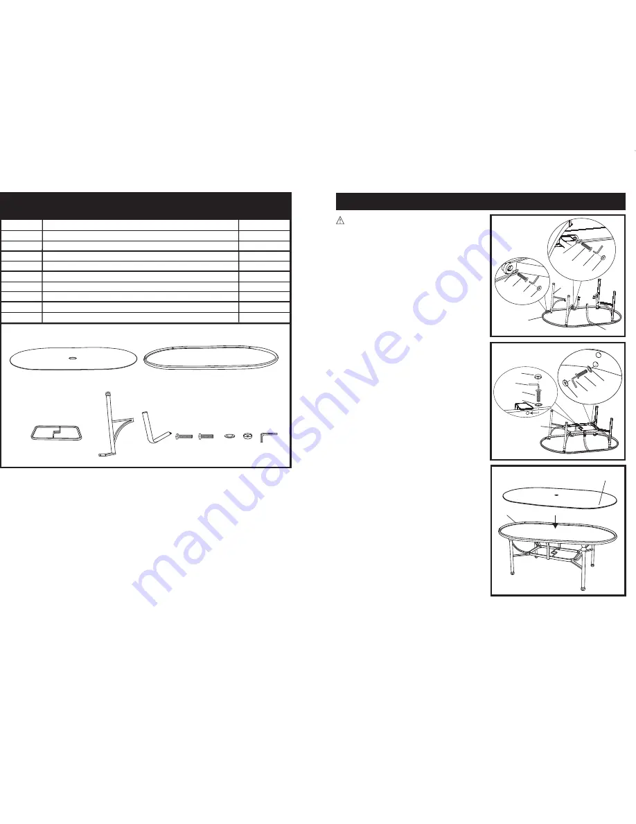
Figure 1
Figure 2
Figure 3
PARTS & HARDWARE LIST
PART #
DESCRIPTION
QUANTITY
A Glass
1
B Table
Rim
1
C Center
Support
1
D Legs
4
E Table
Support
2
F
Bolts M6 x 25
12
G
Bolts M6 x 15
12
H Washers
24
I Bolt
Cover
24
J Hex
Key
1
Carefully remove the contents from the package. If any parts are missing do not
attempt to use the product until they have been obtained and correctly installed.
Parts Detail
1
NOTE:
This product is intended for residential, non-commercial use.
2
B
B
B
D
D
E
E
F
H
J
G
I
H
H
J
J
G
G
I
I
F
H
J
I
F
H
J
I
1.
(SEE FIGURE 1)
Place the table rim (B) upside
down on a flat non-scratch surface then
attach legs (D) with bolts (G) and washers (H)
using hex key (J). Attach table support (E)
with bolts (G) and washers (H) using
hex key (J).
2.
(SEE FIGURE 2)
Insert the center support (C)
in between legs (D) and table support (E) and
secure with bolts (F) and washers (H) using
hex key (J).
3.
(SEE FIGURE 3)
Turn table upright and carefully
set glass (A) into the table rim (B). Tighten
fasteners around the center support (C) in a
cross corner fashion to level the table and
secure for use. Apply bolt covers (I) to all
exposed
bolts.
CAUTION:
Do not over tighten fasteners.


