DRV-28 inverter
s Basic operartion instructions
-94-
Set
value
Function
Description
setting can clear the frequency value of auxiliary channel
set by UP/DOWN, thus restoring the reference frequency
to the frequency given by main reference frequency
command channel.
13
Switching between A setting
and B setting
This function is used to switch between the frequency
setting channels.
A frequency reference channel and B frequency
reference channel can be switched by no. 13 function;
the combination channel set by P00.09 and the A
frequency reference channel can be switched by no. 14
function; the combination channel set by P00.09 and the
B frequency reference channel can be switched by no. 15
function.
14
Switching between
combination setting and A
setting
15
Switching between
combination setting and B
setting
16
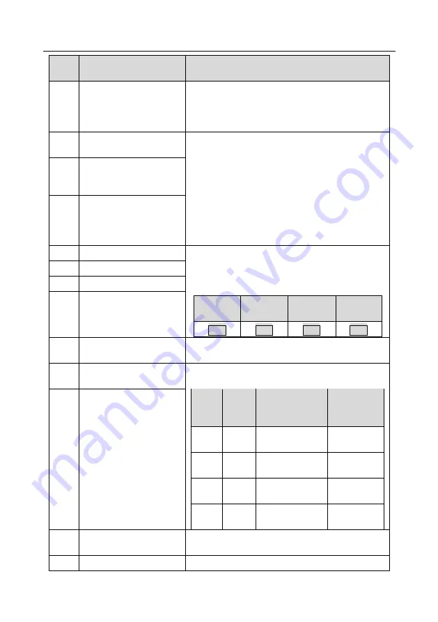
Multi-step speed terminal 1 16-step speeds can be set by combining digital states of
these four terminals.
Note: Multi-step speed 1 is low bit, multi-step speed 4
is high bit.
Multi-step
speed 4
Multi-step
speed 3
Multi-step
speed 2
Multi-step
speed 1
BIT3
BIT2
BIT1
BIT0
17
Multi-step speed terminal 2
18
Multi-step speed terminal 3
19
Multi-step speed terminal 4
20
Multi-step speed pause
Pause multi-step speed selection function to keep the set
value in present state.
21
Acceleration/deceleration
time selection 1
Use these two terminals to select four groups of
acceleration/decoration time.
Terminal
1
Terminal
2
Acceleration or
deceleration time
selection
Corresponding
parameter
OFF
OFF
Acceleration/
deceleration time 1
P00.11/P00.12
ON
OFF
Acceleration/
deceleration time 2
P08.00/P08.01
OFF
ON
Acceleration/
deceleration time 3
P08.02/P08.03
ON
ON
Acceleration/
deceleration time 4
P08.04/P08.05
22
Acceleration/deceleration
time selection 2
23
Simple PLC stop reset
Restart simple PLC process and clear previous PLC
state information.
24
Simple PLC pause
The program pauses during PLC execution, and keeps


