DRV-28 inverter
s Basic operartion instructions
-99-
Function
code
Name
Detailed parameter description
Default
value
BIT3: S4 virtual terminal
BIT4: HDIA virtual terminal
BIT8: HDIB virtual terminal
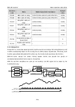
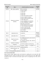
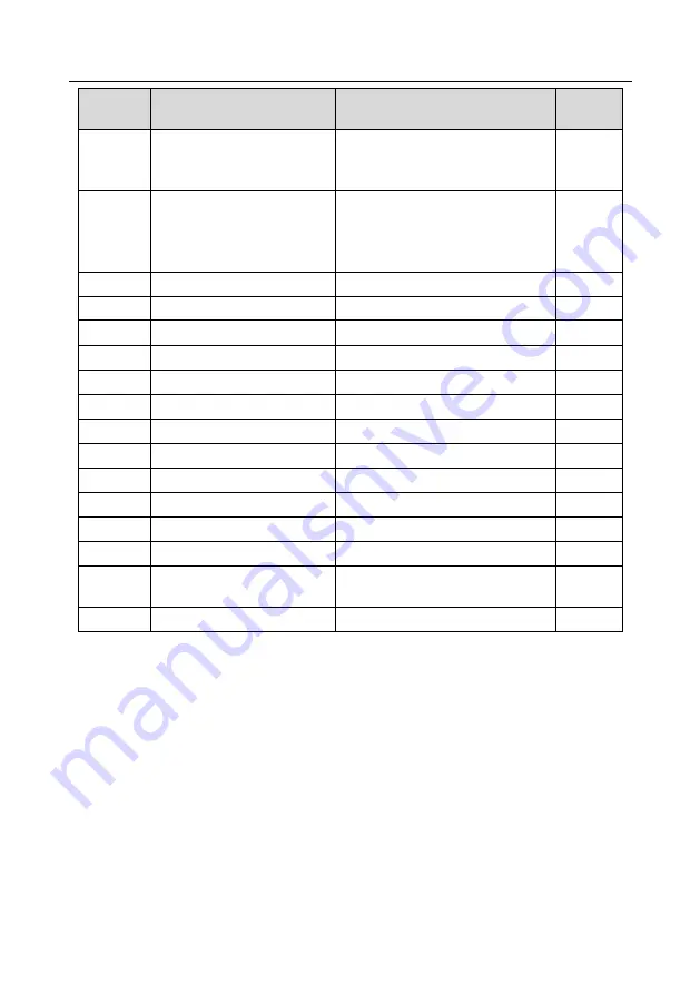
P05.11
2/3-wire control mode
0: 2-wire control 1
1: 2-wire control 2
2: 3-wire control 1
3: 3-wire control 2
0
P05.12
S1 terminal switch-on delay
0.000
–50.000s
0.000s
P05.13
S1 terminal switch-off delay
0.000
–50.000s
0.000s
P05.14
S2 terminal switch-on delay
0.000
–50.000s
0.000s
P05.15
S2 terminal switch-off delay
0.000
–50.000s
0.000s
P05.16
S3 terminal switch-on delay
0.000
–50.000s
0.000s
P05.17
S3 terminal switch-off delay
0.000
–50.000s
0.000s
P05.18
S4 terminal switch-on delay
0.000
–50.000s
0.000s
P05.19
S4 terminal switch-off delay
0.000
–50.000s
0.000s
P05.20
HDIA terminal switch-on delay 0.000–50.000s
0.000s
P05.21
HDIA terminal switch-off delay 0.000–50.000s
0.000s
P05.22
HDIB terminal switch-on delay 0.000–50.000s
0.000s
P05.23
HDIB terminal switch-off delay 0.000–50.000s
0.000s
P07.39
Input terminal state of present
fault
/
0
P17.12
Digital input terminal state
/
0
5.5.12 Digital output
DRV-28 series inverter carries two groups of relay output terminals, one open collector Y output
terminal and one high-speed pulse output (HDO) terminal. The function of all the digital output
terminals can be programmed by function codes, of which the high-speed pulse output terminal HDO
can also be set to high-speed pulse output or digital output by function code.


