DRV-28 inverter
s Function parameter list
-177-
Function
code
Name
Detailed parameter description
Default
value
Modi
fy
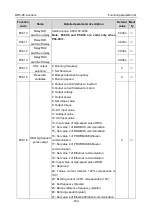
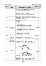
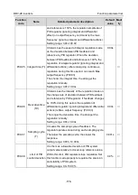
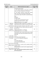
signal of controlled system.
The system operates based on the relative value (0–
100.0%)
P09.01
Pre-set PID
reference of
keypad
Users need to set this parameter when P09.00 is set
to 0, the reference value of this parameter is the
feedback variable of the system.
Setting range: -100.0%–100.0%
0.0%
○
P09.02
PID feedback
source
This parameter is used to select PID feedback
channel.
0: AI1
1: AI2
2: AI3
3: High-speed pulse HDIA
4: MODBUS communication
5: PROFIBUS/CANopen/DeviceNet communication
6: Ethernet communication
7: High-speed pulse HDIB
8: EtherCat/Profinet communication
9: Programmable extension card
10: Reserved
Note: The reference channel and feedback
channel cannot overlap; otherwise, PID cannot
be controlled effectively.
0
○
P09.03
PID output
characteristics
0: PID output is positive characteristic: namely, the
feedback signal is larger than the PID reference,
which requires the inverter output frequency to
decrease for PID to reach balance, eg, tension PID
control of winding
1: PID output is negative characteristics: namely the
feedback signal is less than PID reference, which
requires inverter output frequency to increase for
PID to reach balance, eg, tension PID control of
unwinding.
0
○
P09.04
Proportional gain
(Kp)
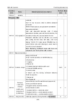
This function code is suitable for proportional gain P
of PID input.
It determines the regulation intensity of the whole
PID regulator, the larger the value of P, the stronger
the regulation intensity. If this parameter is 100, it
means when the deviation between PID feedback
1.80
○

