DRV-28 inverter
s Extension cards
-300-
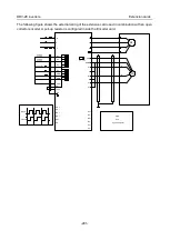
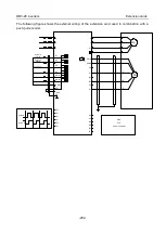
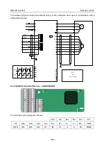
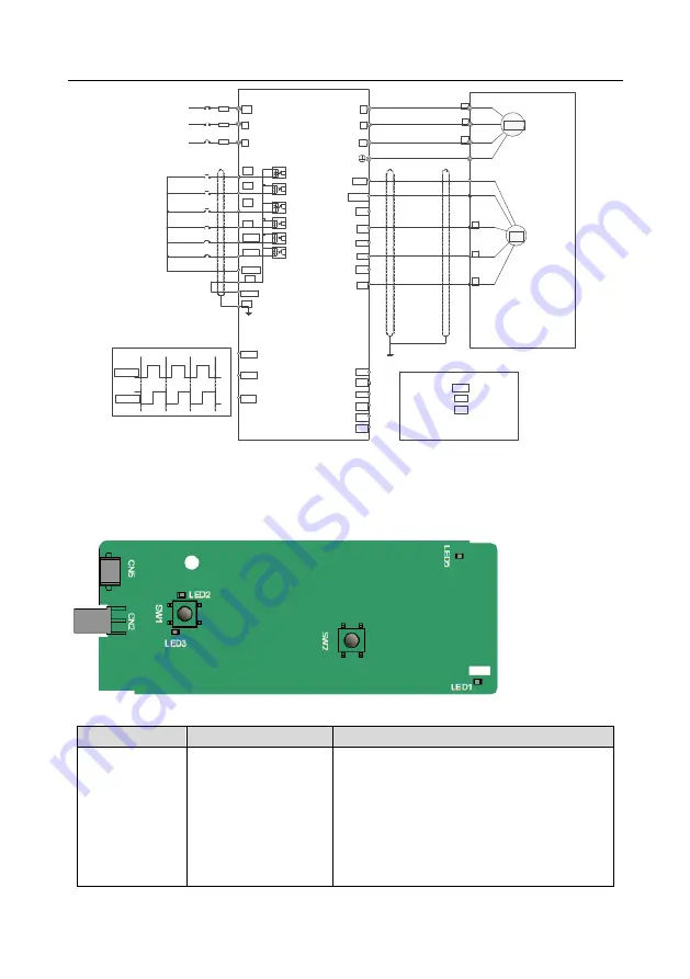
+24V
PE
COM
S4
S3
S2
S1
HDIB
PW
HDIA
A1-
B1+
B1-
Z1+
Z1-
R
S
T
U
V
W
U
V
W
M3~
PG
AO
BO
ZO
pulse A
pulse B
A2+
A2-
B2+
B2-
CNC
PLC
A1+
Z2+
Z2-
PGND
PWR
Z
B
A
PLC
Forward running
Forward jogging
Fault reset
A.6 Communication card function description
A.6.1 Bluetooth communication card
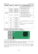
–– AS28BTH000x and WIFI card ––
AS28WIF000x
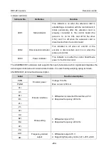
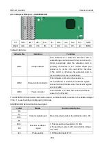
Definitions of indicators and function buttons:
Indicator No.
Definition
Function
LED1/LED3
Bluetooth/WIFI state
indicator
LED1 is on when the extension card is
establishing a connection with the control board;
LED1 blinks periodically after the extension card
is properly connected to the control board (the
period is 1s, on for 0.5s, and off for the other
0.5s); and LED1 is off when the extension card
is disconnected from the control board.

