DRV-28 inverter
s STO function description
-336-
Appendix E STO function description
Reference standards: IEC 61508-1, IEC 61508-2, IEC 61508-3, IEC 61508-4, IEC 62061, ISO
13849-1, and IEC 61800-5-2
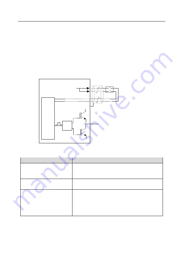
You can enable the safe torque off (STO) function to prevent unexpected startups when the main
power supply of the drive is not switched off. The STO function switches off the drive output by turning
off the drive signals to prevent unexpected startups of the motor (see the following figure). After the
STO function is enabled, you can perform some-time operations (such as non-electrical cleaning in
the lathe industry) and maintain the non-electrical components of the device without switching off the
drive.
Control
circuit
+24V
Switch, relay, etc.
UDC+
UDC-
Drive
circuit
PWM+
PWM-
U/V/W
H1
H2
Note:
The contacts of the safety switch must be opened
o r c l o s e d w i t h i n 2 5 0 m s ; a n d t h e c a b l e t h a t
connects the inverter to the safety switch cannot be
longer than 25 m.
COM
E.1 STO function logic table
The following table describes the input states and corresponding faults of the STO function.
STO input state
Corresponding fault
H1 and H2 opened
simultaneously
The STO function is triggered, and the drive stops running.
Fault code:
40: Safe torque off (STO)
H1 and H2 closed
simultaneously
The STOP function is not triggered, and the drive runs
properly.
One of H and H2 opened, and
the other closed
The STL1, STL2, or STL3 fault occurs.
Fault code:
41: Channel H1 exception (STL1)
42: Channel H2 exception (STL2)
43: Channel H1 and H2 exceptions (STL3)
E.2 STO channel delay description
The following table describes the trigger and indication delay of the STO channels.


