DRV-28 inverter
s Basic operartion instructions
-72-
Function
code
Name
Detailed parameter description
Default
value
keypad
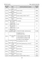
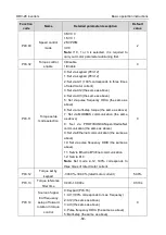
P17.09
Motor output
torque
-
250.0–250.0%
0.0%
P17.15
Torque reference
value
-
300.0–300.0% (rated motor current)
0.0%
5.5.6 Motor parameter
Check the safety conditions surrounding the motor and load machineries
before autotuning as physical injury may occur due to sudden start of motor during
autotuning.
Although the motor does not run during static autotuning, the motor is stilled
supplied with power, do not touch the motor during autotuning; otherwise, electric
shock may occur.
If the motor has been connected to load, do not carry out rotary autotuning;
otherwise, misact or damage may occur to the inverter. If rotary autotuning is carried
out on a motor which has been connected to load, wrong motor parameters and
motor misacts may occur. Disconnect the load to carry out autotuning if necessary.
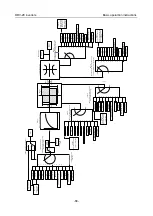
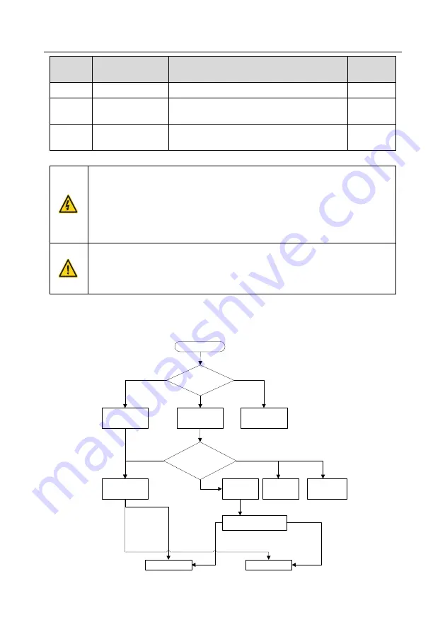
DRV-28 inverter can drive asynchronous motors and synchronous motors, and it supports two sets of
motor parameters, which can be switched over by multi-function digital input terminals or
communication modes.
Keypad (P00.01=0)
Terminal
(P00.01=1)
Communication
(P00.01=2)
MODBUS
communication
PROFIBUS
CANopen
communication
Start
Select running
command channel
(P00.01)
The switch-over
channel for motor 1 and
motor 2 (P08.31)
Terminal function 35
Motor 1 switches to
motor 2
Communication setting value
2009H
Motor 1
Motor 2
Invalid
Valid
BIT0
–
1=00
BIT0
–
1=01
P08.31 set LED
ones to 0
Ethernet
communication
P08.31 set LED
ones to 1
P08.31 sets
ones to 2
P08.31 sets
ones to 3


