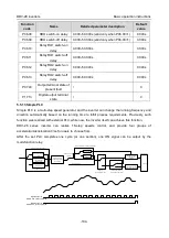
DRV-28 inverter
s Basic operartion instructions
-89-
0
1
2
3
.
.
.
.
.
.
19
20
P06.14
P06.16
AO1
HDO
P06.17
P06.18
P06.19
P06.20
P06.27
P06.28
P06.29
P06.30
P06.21
P06.31
(Default value is 0)
(Default value is 0)
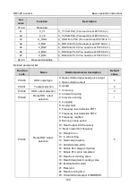
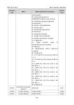
P06.00
(HDO output type)
0
1
P06.00
0: Open collector high-speed
pulse output
1: Open-collector output
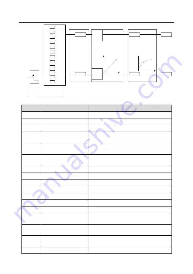
Analog output curve setting
Analog output selection
Analog output filter
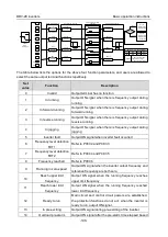
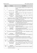
Instructions for output:
Set value
Function
Description
0
Running frequency
0–Max. output frequency
1
Set frequency
0–Max. output frequency
2
Ramps reference frequency 0–Max. output frequency
3
Running speed
0–Synchronous speed corresponding to Max. output
frequency
4
Output current (relative to
inverter)
0–Two times of rated current of inverter
5
Output current (relative to
motor)
0–Two times of rated current of motor
6
Output voltage
0–1.5 times of rated voltage of inverter
7
Output power
0–Two times of rated power
8
Set torque value
0–Two times of rated current of motor
9
Output torque
0–Two times of rated current of motor
10
AI1 input value
0–10V/0–20mA
11
AI2 input value
-
10V–10V
12
AI3 input value
0–10V/0–20mA
13
Input value of high-speed
pulse HDIA
0.00–50.00kHz
14
Set value 1 of MODBUS
communication
-
1000–1000, 1000 corresponds to 100.0%
15
Set value 2 of MODBUS
communication
-
1000–1000, 1000 corresponds to 100.0%
16
Set value 1 of
-
1000–1000, 1000 corresponds to 100.0%


