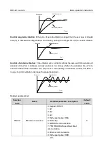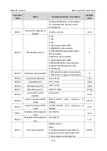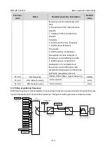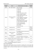
DRV-28 inverter
s Function parameter list
-125-
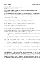
Chapter 6 Function parameter list
6.1 What this chapter contains
This chapter lists all the function codes and corresponding description of each function code.
6.2 Function parameter list
Function parameters of DRV-28 series inverter are categorized according to functions. Among the
function groups, P98 is analog input/output calibration group, and P99 is factory function group which
cannot be accessed by users. The function code adopts three-level menu, eg, "P08.08" indicates it is
the no. 8 function code in P8 group.
The function group no. corresponds to the first-level menu; function code no. corresponds to the
second-level menu; function code parameter corresponds to the third-level menu.
1.
The function list is divided into the following columns.
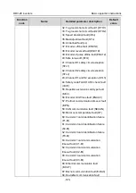
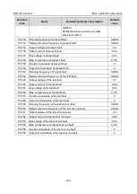
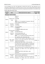
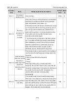
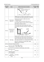
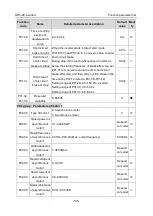
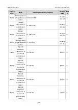
Column 1 "Function code": number of the function parameter group and the parameter;
Colum 2 "Name": complete name of the function parameter;
Colum 3 "Detailed parameter description": detailed description of this function parameter;
Colum 4 "Default value": The original set value of the function parameter by default;
Colum 5: "Modify": The modification attribute of the function parameter, namely whether the function
parameter can be modified and the condition for modification, as shown below.
"
○
": the set value of this parameter can be modified when the inverter is in stop or running
state;
"
◎
": the set value of this parameter cannot be modified when the inverter is in running state;
"
●
": the parameter value is the measured value which cannot be modified.
(The inverter has assigned the modification attribute of each parameter automatically to avoid
inadvertent modification by users.)
2.
"System of numeration for parameters" is decimal; if the parameter is presented in
hexadecimal numbers, the data of each bit will be independent of each other during parameter
edit, and the value range of partial bits can be 0–F in hexadecimal system.
3.
"Default value" is value restored after parameter refresh during restoring to default value;
however, the measured value or recorded value will not be refreshed.
4.
In order to enhance parameter protection, the inverter provides password protection for the
function codes. After setting user password (namely user password P07.00 is not zero), when users
press PRG/ESC key to enter function code edit state, the system will first enter user password
verification state which displays "0.0.0.0.0.", requiring operators to input the correct user password.
For factory parameters, besides user password, it is also required to input the correct factory
password (users should not attempt to modify factory parameters as improper setup may easily lead
to mal-operation or damage the inverter). When password protection is unlocked, the user password

