Communication extension card
-56-
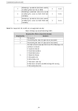
Item
Color
Function description
indicator
(OUT)
established.
On: Indicates that Ethernet connection is established
successfully.
Green
Off: Without connection
On: Wilth connection but inactive
Blinks: With connection and active
4.7
Electrical wiring
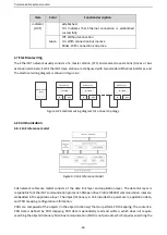
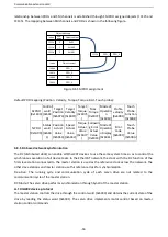
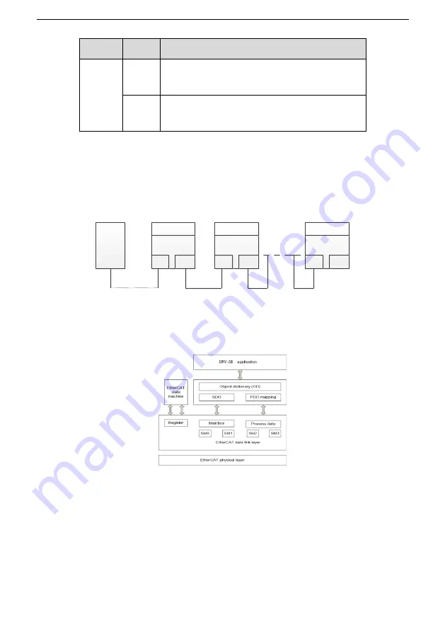
The EtherCAT network usually consists of a master station (PLC) and several slave stations (drives or bus
extension terminals). Each EtherCAT slave station are configured with two standard Ethernet interfaces, and
the electrical wiring diagram is shown in Figure 6-2.
Master device
(PLC)
Slave device 1
EC-Tx508
IN
OUT
Slave device 2
EC-Tx508
IN
OUT
Slave device n
EC-Tx508
IN
OUT
Figure 0-2
Electrical wiring diagram for a linear topology
4.8
Communication
4.8.1
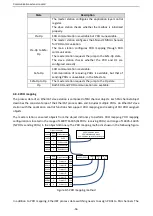
CoE reference model
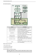
Figure 0-3 CoE reference model
CoE network reference model consists of the data link layer and application layer. The data link layer is
responsible for EtherCAT communication protocol. CANopen drive Profile (DS402) communication rules are
embedded in the application layer. The object dictionary in CoE includes the parameters, application data,
and PDO mapping configuration information.
PDOs are composed of the objects (in the object dictionary) that can perform PDO mapping. The content in
PDO data is defined by PDO mapping. PDO data is periodically read and written, which does not require
searching the object dictionary. Mail box communication (SDO) is not periodic, which requires searching the


