Communication extension card
-4-
package (DIP) switch on the printed circuit board (PCB) of a communication card is used to connect to
the fieldbus terminator. If the communication card is the last or first module on the network, the bus
terminator must be set to ON. When a PROFIBUS D-sub connector with a built-in terminator is used,
you must disconnect the communication card from the terminator.
2.4
Bus network connection
1.
Bus communication interfaces
The most common PROFIBUS transmission mode is the shielded twisted-pair copper cable transmission,
in which shielded twisted-pair copper cables (complying with the RS-485 standard) are used.
The basic characteristics of this transmission technology are described as follows:
•
Network topology: Linear bus with one active fieldbus terminal resistor on each end
•
Transmission rate: 9.6 kbit/s
–
12 Mbit/s
•
Media: Shielded or unshielded twisted-pair cables, depending on the EMC environmental conditions
•
Number of stations: 32 on each network segment (without repeater); a maximum of 127 (with
repeaters)
•
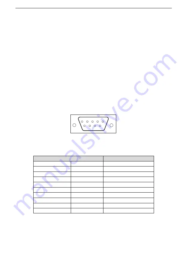
Plug connection: 9-pin D-type plug. The following figure shows the pins of the connector.
•
1
5
4
3
2
9
8
7
6
Figure 2-1 Plug of the connector
Table 2-1 Connector pins
Connector pin
Description
1
-
Unused
2
-
Unused
3
B-Line
Data+ (twisted-pair wire 1)
4
RTS
Transmitting requests
5
GND_BUS
Isolation ground
6
+5V BUS
Isolated 5 V DC power supply
7
-
Unused
8
A-Line
Data- (twisted-pair wire 2)
9
-
Unused
Housing
SHLD
PROFIBUS cable shielding wire
The +5V and GND_BUS pins are used for bus terminators. Optical transceivers (RS-485) and some other
devices may need to obtain external power supplies through these pins.
For some devices, the transmission direction is determined by using the RTS pin. In regular application, only
the A-Line, B-Line, and SHLD pins are used.
It is recommended that you use the standard DB9 connectors manufactured by Siemens. If the


