AS64 series AC servo drive Function codes
-113-
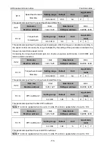
P1.36
Vibration control
frequency 1
Setting
range
Default
Unit
Applicable
mode
0.0–200.0
0.0
Hz
P
This parameter specifies the frequency at which the vibration at the load peak is suppressed.
Note:
The frequency must range from 1.0 Hz to 200.0 Hz.
P1.36
Data size
16bit
Data format
DEC
Modbus address
1272, 1273
CANopen address
0x2124, 0x00
P1.37
Coefficient of
vibration control filter
1
Setting
range
Default
Unit
Applicable
mode
0.00–1.00
1.00
-
P
This parameter specifies the coefficient of the first vibration control filter.
P1.37
Data size
16bit
Data format
DEC
Modbus address
1274, 1275
CANopen address
0x2125, 0x00
P1.38
Vibration control
frequency 2
Setting
range
Default
Unit
Applicable
mode
0.0–200.0
0.0
Hz
P
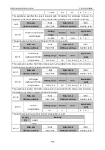
P1.39
Coefficient of
vibration control filter
2
Setting
range
Default
Unit
Applicable
mode
0.00–1.00
1.00
-
P
This group of parameter specifies the characteristics of the second vibration control filter. They
are similar to P1.36 and P1.37.
P1.38
Data size
16bit
Data format
DEC
Modbus address
1276, 1277
CANopen address
0x2126, 0x00
P1.39
Data size
16bit
Data format
DEC
Modbus address
1278, 1279
CANopen address
0x2127, 0x00
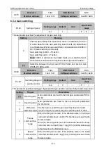
6.3 Motor control (group P2)
6.3.1 Gain settings
P2.00
Speed gain 1
Setting
range
Default
Unit
Applicable
mode
0.0–3276.7
27.0
Hz
P
S
T
The speed loop responsiveness of the servo system is determined by the speed gain. Increasing
this parameter improves the speed response, but it increases the possibility to cause vibration
and noise.
Note:
If the inertia ratio is set correctly, the unit of P2.00 is Hz.
P2.00
Data size
16bit
Data format
DEC


