background image

4. ASSEMBLY:  

 
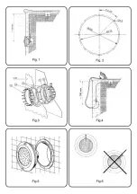
After installation of the housing and the clamp, if it is a prefabricated swimming pool, assemble the floodlamp. 
To connect the floodlamp to the electric power supply insert the cable through the gland seal nut (16). Tighten the 
gland seal nut until you can verify that the cable will not yield when you pull on it with your hand. 
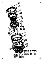
Take the precaution of leaving 1.5 m of cable wound on the base of the floodlamp (no. 7) in order to be able to 
remove the floodlamp to the edge of the pool in the event that lamp replacement or handling is required. (Fig. 4). 
Insert the entire floodlamp assembly in the housing (Fig 5). In order to obtain good pool lighting it is important that 
the anagram of the decorative ring (no. 1) is located on the upper part (Fig 6). 
Screw in the two M-6 x 80 screws (no. 2) until the fastening dog is secured in the inner walls of the housing (Fig. 7) 
 

5. MAINTENANCE: 

 
To remove the floodlamp to the edge of the swimming pool (Fig. 5) loosen the two DIN 966 M-6 x 80 screws (no. 2) 
until the fastening dog yields sufficiently so that the floodlamp unit can be separated from the housing. 
To remove the lamp, unscrew the 6 nuts (no. 9) which secure the decorative ring (no. 1) to the base of the floodlamp 
(no. 7) (Fig. 8). 
Remove the lamp (no. 5) from the inside of the base of the floodlamp and disconnect the two terminals, loosening 
the two screws which secure them to the lamp (Fig. 9). 
Change the lamp and assemble the Floodlamp, in the opposite order described in point 4 of assembly, taking special 
care to: 

• 

Connect the cable terminals to the lamp, using the 2 screws supplied with the lamp (Fig. 10). 

• 

Fully centre the 110x11 O-ring (no. 6) in its seat. 

• 

Firmly tighten the nuts. 

Attention: 

• 

Before any handling ensure that there is NO voltage supplied to the floodlamp. 

• 

The new lamp should have the same characteristics as that supplied with the floodlamp, PAR 56 300 W 12 V. 

• 

In order to ensure full watertightness, clean the seat of the O-ring (no. 6) for the lamp or replace the O-ring if you 
observe any notches or permanent damage. 


6. START-UP:  

 
Ensure that the voltage the lamp receives is never greater than 12 V. 
The floodlamp should only operate underwater while secured to the vertical walls of the pool. Never switch on the 
floodlamp if it is not underwater. 
 

7. SAFETY WARNINGS: 


• 

The persons who are in charge of assembly should have the required qualificatlons for this type of work. 

• 

Avoid making contact with the electric voltage. 

• 

Comply with the current standards regarding accident prevention. 

• 

In this regard, the IEC 364-7-702 standards must be observed. WIRING IN BUILDINGS. SPECIAL WIRING. 
SWIMMING POOLS. 

• 

Any operation related to the maintenance or replacement of parts should be performed with the floodlamp 
disconnected from the electric power system. 

• 

Do not handle with wet feet. 

• 

The manufacturer is not responsible in any circumstances for assembly, installation or start-up of any electric 
components which have been inserted or handled at locations other than Its own premises.


• 

It is recommended not to use sealing filler in this product and in any case. only use products specifically designed 
to work with ABS. Universal products should not be used.


Summary of Contents for 23672

Page 1: ...O SUBACQUEO UNTERWASSER SCHEINWERFER FARO SUBACQUEO INSTALLATION AND MAINTENANCE MANUAL MANUEL D INSTALLATION ET D ENTRETIEN MANUAL DE INSTALACI N Y MANTENIMIENTO MANUALE DI INSTALAZIONE E MANUTENZION...

Page 2: ...n its own premises 3 INSTALLATION Never install the lamp facing downwards In order to clearly light a pool it is recommended lo install a 300W floodlamp every 25 or 35 m of water surface In swimming p...

Page 3: ...assembly taking special care to Connect the cable terminals to the lamp using the 2 screws supplied with the lamp Fig 10 Fully centre the 110x11 O ring no 6 in its seat Firmly tighten the nuts Attenti...

Page 4: ...rajout de composants lectriques qui ne se seraient pas produits chez lui 3 INSTALLATION Ne jam is installer la lampe orient e vers le bas Pour assurer un bon clairage une piscine il est recommand d i...

Page 5: ...s 2 vis fourmes avec la lampe Fig 10 Placer le joint torique 110x11 num 6 bien centr dans son logement Bien serrer tous les crous Attention Avant toute manipulation s assurer que le projecteur N EST P...

Page 6: ...raci n de componentes el ctricos que no se hayan llevado a cabo en sus instalaciones 3 INSTALACI N No instalar nunca con la l mpara hacia abajo Para iluminar claramente una piscina se recomienda insta...

Page 7: ...trados con la l mpara Fig 10 Poner la Junta t rica 110x11 n 6 bien centrada en su alojamiento Apretar bien todas las tuercas Atenci n Antes de cualquier manipulaci n asegurarse que el proyector NO rec...

Page 8: ...ati o introdotti al di fuori dei suoi stabilimenti 3 INSTALLAZIONE Non installare mal con la lampada verso il basso Per ben iIluminare una piscina si raccomanda d installare un proiettore da 300W per...

Page 9: ...mpada usando le due viti fornite con la lampada Fig 10 Metiere a guarnizione tonca 110x11 n 6 ben centrata nel suo allogglamento Stnngere bene tutti i dadi Attenzione Prima di qualsiasi manipolazione...

Page 10: ...gendeine Art Handhabung oder Einbau von Elektrokomponenten nicht in seinem Betrieb durchgef hrt worden sind 3 INSTALLATION Der Strahler darf nie in vertikaler Lage mit der Lampe nach unten weisend Ins...

Page 11: ...angeschlossen wof r die beiden mit der Lampe mitgelieferten Schrauben zu verwenden sind Abb 10 Die Rundringdichtung 110x11 Nr 6 mu gut zentriert in ihre Aufnahme gelegt werden Die Schrauben m ssen gut...

Page 12: ...or qualquer manipula o ou incorpora o de componentes el ctricos que n o tenham sido realizadas as suas instala oes 3 INSTALA O N o instalar nunca com a l mpada para baixo Para iluminar claramente uma...

Page 13: ...10 Colocar a Junta t rica 110x11 n 6 bem centralizada no seu alojamento Apertar bem todas as porcas Aten o Antes de qualquer manipula o assegure se de que o projector N O recebe tens o A l mpada nova...

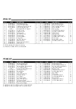
Page 14: ...21 27 26 19 18 16 14 15 1 2 4 3 5 6 7 25 24 23 17 28 20 18 9 8 12 10 13 11 22 16 15 14...

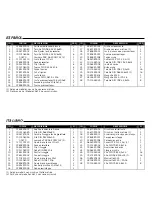
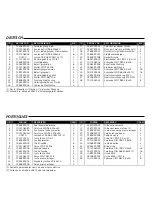
Page 15: ...models with metric pitch housing 2 Pieces that in Model 23672 are not provided FRAN AIS ID CODE DESCRIPTION Q ID CODE DESCRIPTION Q 1 07838R0001 Anneau enjoliver blanc 1 17 23670R0002 Niche autovissa...

Page 16: ...opas 2 1 Solo para modelos con nicho con rosca m trica 2 Piezas que en el Modelo 23672 no se suministran ITALIANO ID CODICE DESCRIZIONE Q ID CODICE DESCRIZIONE Q 1 07838R0001 Anello ornamentale bianco...

Page 17: ...astik 2 16 07838R0005 Schraube Stopfbuchse 2 1 Nur f r Modelle mit Nische mit metrischer Windung 2 St cke die in Modell 23672 nicht vorausgesetzt werden PORTUGUES ID CODIGO DESCRI O CAN ID CODIGO DESC...

Page 18: ......

Page 19: ......
Page 20: ...R NUNCA EL PROYECTOR SI NO ESTA SUMERGIDO EN AGUA NON ACCENDERE MAI IL PROIETTORE SE NON IMMERSO IN ACQUA UNTERWASSER SHEINWERFER NUR UNTER WASSER GETAUCHT ANZUMACHEN NAO ACENDER NUNCA O PROECTOR SE N...

Reviews: