- 32 -
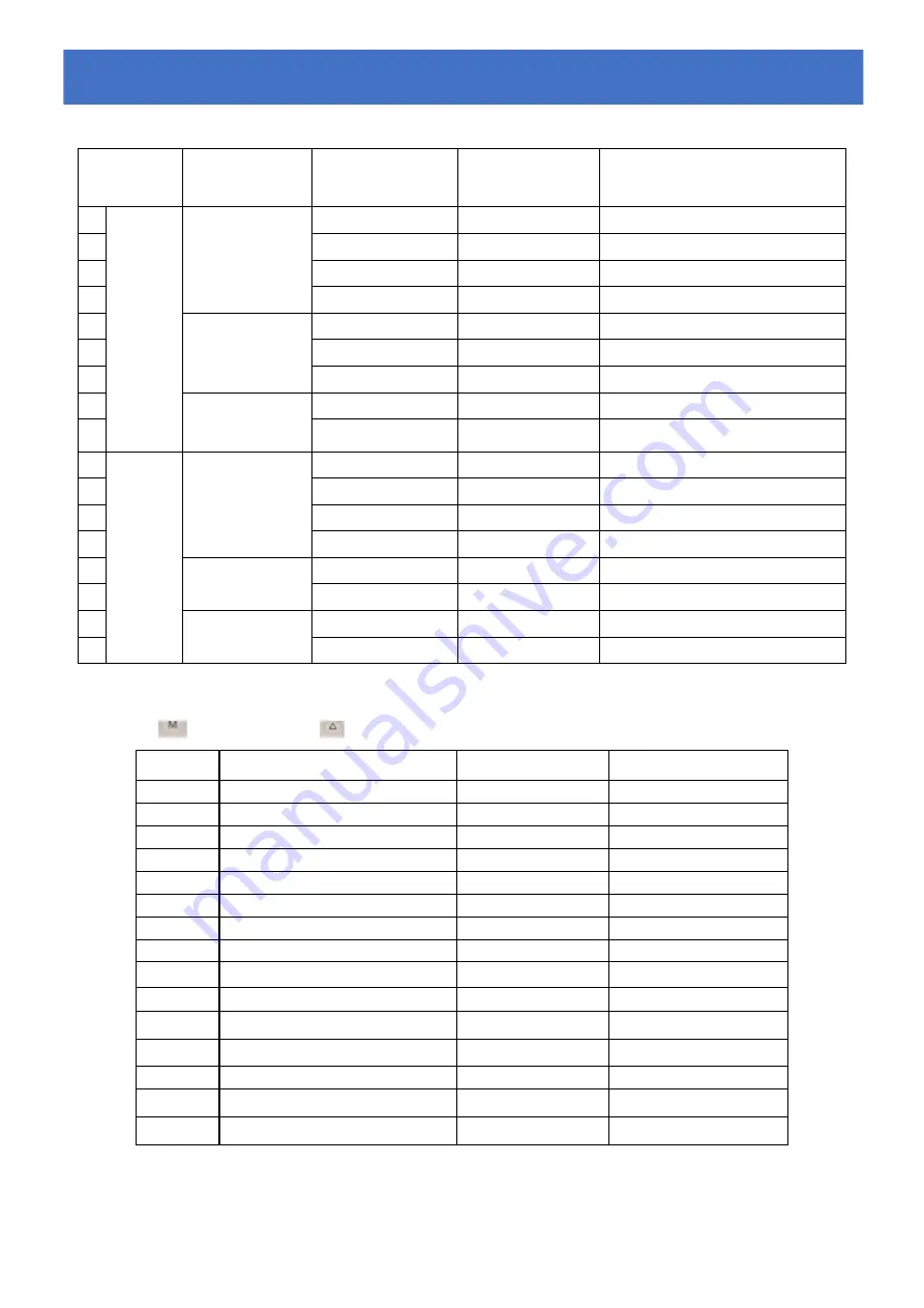
7.5.5. Cooling operation logic
Working
status
Working mode
Water in
temperature
For example ,
water in
temperature
Heat pump working level
1
Start-up
of heat
pump
When you select
the "Smart
working mode "
T1
≦
Tset-1
T1
≦
27
℃
Standby.
2
Tset-1<T1
≦
Tset
27
℃
< T1
≦
28
℃
Silent mode-frequency F2
3
Tset<T1
≦
Tset+1
28< T1
≦
29
℃
frequency
:
F9 -F8-F7,...,- F2
4
T1
≧
Tset+1
T1
≧
29
℃
Powerful mode-F9
5
When you select
the "Silent
working mode".
T1
≦
Tset-1
≦
27
℃
Standby
6
Tset-1<T1
≦
Tset
27
℃
< T1
≦
28
℃
Silent mode - frequency F2/F1
7
T1>Tset
T1>28
℃
Smart mode -frequency F5
8
When you select
the "Powerful
working mode."
T1>Tset-1
T1>27
℃
Powerful mode-frequency F10/F9
9
T1
≦
Tset-1
T1
≦
27
℃
Standby
10
Re-start
to cool
water in
standby
status
Smart
T1
≦
Tset-1
T1
≦
27
℃
Standby
11
Tset
≦
T1 <Tset+1 28
≦
T1 <29
℃
Silent- frequency F2
12
Tset+1
≦
T1 <Tset+2 29
≦
T1 <30
℃
Frequency: F2 -F3-F4,...,- F9
13
T1
≧
Tset+2
T1
≧
30
℃
Powerful mode -frequency F9
14
Silent
Tset<T1
≦
Tset+1
28< T1
≦
29
℃
Silent mode-frequency F2/F1
15
T1
>
Tset+1
T1
>
29
℃
Smart mode-frequency F5
16
Powerful
T1
>
Tset+1
T1
>
29
℃
Powerful mode-frequency F10/F9
17
T1
≦
Tset-1
T1
≦
27
℃
Standby
7.6. Parameter checking or setting
7.6.1 Press
5S and then press
to check the parameter from d0-d14.
Code
Parameter
Range
Remark
d0
IPM module temperature
0-120
℃
Real value
d1
Water inlet temp.
-9
℃~
99
℃
Real value
d2
Water outlet temp.
-9
℃~
99
℃
Real value
d3
Ambient temp.
-30
℃~
70
℃
Real value<-9 flash
d4
Frequency limitation code
0,1,2,4,8,16
Real value
d5
Coil temperature
-30
℃~
70
℃
Real value<-9 flash
d6
Gas exhaust temperature
0
℃~
125
℃
Real value
d7
Step of EEV
0
~
99
N*5
d8
Compressor running frequency
0
~
99Hz
Real value
d9
Compressor current
0
~
30A
Real value
d10
Current fan speed
0-1200
(
rpm
)
Real value
d11
Error code for last time
All error code
d12
MODBUS COM
0 - 5
Only Modbus function
d13
MODBUS ID Address.
1 - 88
Only Modbus function
d14
Product code parameter
001- 999
Only Modbus function
7.
7.
7.
Start-up
Start-up
Start-up
of
of
of
the
the
the
Heat
Heat
Heat
Pump
Pump
Pump
Summary of Contents for APH3 INVERBOOST
Page 2: ......
Page 4: ......
Page 12: ... 8 ...
Page 13: ... 9 SWIMMING POOL HEAT PUMP APH3 INVERBOOST R32 gas User and Service manual ...
Page 16: ... 12 Models 68839 68840 1 1 1 Description Description Description ...
Page 50: ... 46 Model 68839 68840 9 9 9 Exploded Exploded Exploded Diagram Diagram Diagram ...
Page 54: ... 50 Pompe à chaleur pour piscine APH3 INVERBOOST R32 Manuel d installation et d utilisation ...
Page 57: ... 53 Models 68839 68840 1 1 1 Descriptif Descriptif Descriptif ...
Page 95: ... 91 Zwembad warmtepomp APH3 INVERBOOST R32 Installatie Instructie Handleiding ...
Page 98: ... 94 Models 68839 68840 1 1 1 Afmetingen Afmetingen Afmetingen ...
Page 132: ... 128 Model 68839 68840 9 9 9 Open Open Open geklapt geklapt geklapt diagram diagram diagram ...
Page 136: ... 132 Bomba de calor para Piscina APH3 INVERBOOST R32 Manual del usuario y de servicio ...
Page 139: ... 135 Modelo 68839 68840 1 Descripción ...
Page 169: ... 165 9 1 Diagrama de despiece Modelo 68837 68838 9 Diagrama de despiece y mantenimiento ...
Page 172: ... 168 9 2 Diagrama de despiece Modelo 68839 68840 9 Diagrama de despiece y mantenimiento ...
Page 176: ... 172 Schwimmbad Wärmepumpe APH3 INVERBOOST R32 Benutzer und Wartungshandbuch ...
Page 179: ... 175 Modell 68839 68840 1 1 1 Beschreibung ...
Page 217: ... 213 POMPA DI CALORE PER PISCINE APH3 INVERBOOST R32 Manuale di Installazione e Uso ...
Page 220: ... 216 Modelli 68839 68840 1 1 1 Description Description Description ...
Page 258: ... 254 BOMBA DE CALOR DE PISCINA APH3 INVERBOOST R32 Manual do utilizador e serviço ...
Page 261: ... 257 Modelos 68839 68840 1 1 1 Dimens Dimens Dimensã ã ão o o ...
Page 312: ......
Page 313: ......


