
7
Viron e-Quilibirum Series Chlorinator
Installation Manual
6
Viron e-Quilibirum Series Chlorinator
Installation Manual
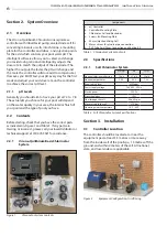
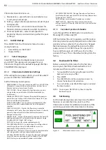
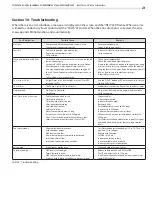
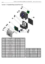
Figure 3.
Equipment Configuration, Acid Dosing and
Optional Sensor Probes
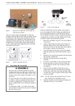
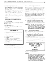
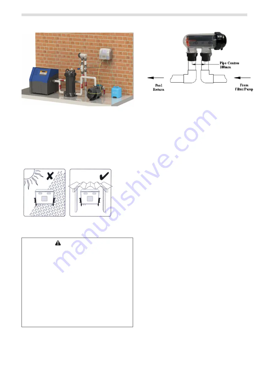
Choose a location that is preferably out of direct
sunlight, near the filter system. The controller should
be located 1 metre above ground level to prevent
rain splash back or sprinkler system damage to the
underside of the controller. The controller must be
mounted on a vertical surface/wall. If mounted on
a post, a flat sheet 20mm larger than the controller
housing must be used.
Figure 4.
Correct Installation Location
3.2
Mounting the Controller
WARNING
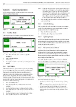
• The cell must be installed horizontally and level.
Improper installation can lead to gas build up which
could result in equipment damage or serious injury.
• The cell must be the last piece of equipment on the
return line.
• It is recommended in all installations that the cell is
installed on a bypass equipped with isolation valves.
• In order to avoid load loss, installing the cell on a
bypass is MANDATORY if system flow rated exceeds
300 Lpm.
• If installing on a bypass, use a downstream check
valve instead of a manual valve to prevent improper
back flow into the cell.
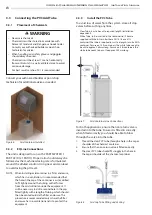
Figure 5.
Correct Cell Installation
Before installing the unit in position on the wall or
post, the length of the PVC tubing provided should
be measured and taken into consideration. Ensure
the controller and cell are close enough for the power
supply lead to reach the cell and sufficient PVC tube
exists to connect acid container and cell.
1.
Mount the wall bracket using the screws provided on
a secure wall.
2.
Glue sensing chamber for probe into plumbing line
after filter and gas heater (if installed) but prior to
chlorinator cell. Sensor Chamber must be plumbed to
ensure probe is horizontal to water flow.
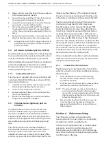
3.
Glue Chlorinator cell into line as per drawing below
after filter, heater, solar (if installed) and after sensor T
piece.
4.
Plug the pH sensor into the underside of the controller
in the location marked “pH”.
5.
Plug filter pump 3 pin plug into underside of
Controller.
6.
Connect 4 wire cell cable ensuring matching colours.
7.
Remove cap from pH sensor and screw firmly into
sensor chamber installed in the plumbing. Do Not
Over tighten.
8.
The cell must be installed with the barrel unions
underneath and the cell should be horizontal. Both
40mm and 50mm fittings have been provided. Make
sure that the o-rings are correctly fitted and the unions
are done up tightly.
NOTE: Direction of water flow through the cell is critical –
refer to label on the controller housing.
9.
Hang the controller on wall bracket and plug power
supply lead into 3 pin 10 amp outlet.


