Installation
900378-00 04/2017
Innovative Hearth Products
MHD35 Series Direct-Vent Gas Fireplaces
26
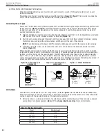
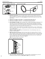
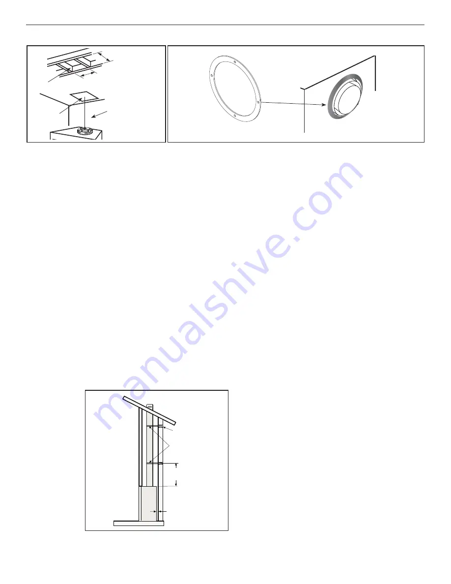
Figure 23 - Framing the ceiling opening
Figure 24 - Rear vent gasket
minimum 10 1/2 in.
(267 mm)
minimum 10 1/2 in.
(267 mm)
Roof
Framing
Ceiling
Framing
Plumb Bob
10-1/2” (267 mm) minimum
10-1/2” (267 mm)
minimum
Gasket
3. Install the rear vent gasket
—The rear vent gasket (Catalog no. F2116) is factory installed and required for
all rear vent applications. If the gasket is missing, position a replacement gasket around the vent collar before
attaching other vent components to the fi replace
(
Figure 24
)
. Loosely attach the gasket with two screws at the
top and bottom.
4. Attach the vent components to the fi replace
—See
Connecting the vent pipe on
Page 22
.
5. Attach the vent components to each other
—See
Connecting the vent pipe on
Page 22
.
6. Install
fi restop/spacer at ceiling
—When using Secure Vent
®
, use SV4.5VF fi restop/spacer at ceiling joists; when
using Secure Flex
®
, use SF4.5VF fi restop/spacer. If there is living space above the ceiling level, the fi restop/
spacer must be installed on the bottom side of the ceiling. If attic space is above the ceiling, the fi restop/spacer
must be installed on the top side of the joist. Route the vent sections through the framed opening and secure the
fi restop/spacer with 8d nails or other appropriate fasteners at each corner.
Remember to maintain 1” (26 mm) clearance to combustibles, framing members, and attic or ceiling insulation
when running vertical chimney sections. The gap between the vent pipe and a vertical fi restop can be sealed with
non-combustible caulking.
NOTE: Attic Insulation Shield (H3907)
must be installed when blown or loose-fi ll insulation is used, and is
required for all attic installations.
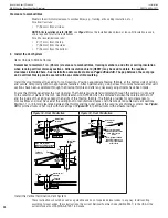
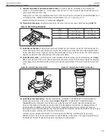
7. Support the vertical vent run sections
—Support the vertical portion of the venting system every 8 ft (2.4 m)
above the fi replace vent outlet. One method of support is by utilizing fi eld provided support straps (conventional
plumber’s tape). Secure the plumber’s tape to the framing members with nails or screws. Loop the tape around
the vent, securing the ends of the tape to the framing. If desired, sheet metal screws #6 x 1/2” length may be
used to secure the support straps to the vent pipe
(
Figure 25
).
NOTE:
Proper venting support is very important.
Figure 25 - Supporting the Vertical Vent Run
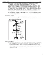
8. Change vent direction of horizontal/inclined run
—Install the SV4.5E45 and SV4.5E90 elbows in the same
manner as the straight vent sections. See
Vent elbows on
Page 22
for more information.
Blocking
Support straps
(plumber’s tape)
8 ft (2.4 m)
maximum
1/2” (13 mm)
minimum
clearance to
combustibles


