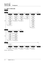
Front panel
OM226131 Rev. A
5
2.2 ALARMS AND OPERATING STATUS
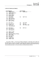
The alphanumeric display offers a complete diagnostic of the system by showing 25
alarms and 6 operating status descriptions.
Each alarm is associated to a code that allows it to be stored in the events history.
A1 MAINS
FAULT
= Rectifier input mains failure
Possible causes: 1) Central system black-out (mains failure)
2) Distribution problems upstream of the UPS
3) RCB open
A2 CHARGER
FAULT
= Battery charger failure
A3 RECT
FUSE
= One or more rectifier fuses are blown
A4 THER IMAGE
= Load transferred to mains due to overload. After 30’
the load is transferred back to inverter
A5 AC/DC
FAULT
= Rectifier output voltage out of tolerance
Possible causes: 1) Mains input voltage too high/low
2) Distribution problems upstream of the UPS
3) RCB open
4) Rectifier bridge failure
A6 INPUT WR SEQ
= Input phase rotation not correct
A7 BCB
OPEN
= Battery circuit breaker open
A8 BATT
DISCH
= The battery is discharging
Possible causes: 1) Rectifier input mains failure (alarm A1 present)
2) Rectifier failure
A9 BATT AUT END
= Battery autonomy (calculated) has expired
A10 BATT FAULT
= Battery test failed
Possible causes: 1) The test has been carried out with the battery not
perfectly charged
2) One or more battery cells are damaged
A11 BATT IN TEST
= Battery test in progress
A12 PLL FAULT
= Problems with the digital synchronisation system
Possible
causes:
1)
Emergency mains excessively disturbed or


