OM226142 rev C
11
The output transformer provides the galvanic insulation between DC and AC side, as well
as voltage adaptation. Its integrated inductance forms, together with the AC capacitors, a
low-pass filter that provides to eliminate the high frequency ripple and keep the total
harmonic distortion of the inverter waveform (THD) lower than 2% (with linear load).
The inverter, thanks to its manufacturing technology and to the microprocessor control, is
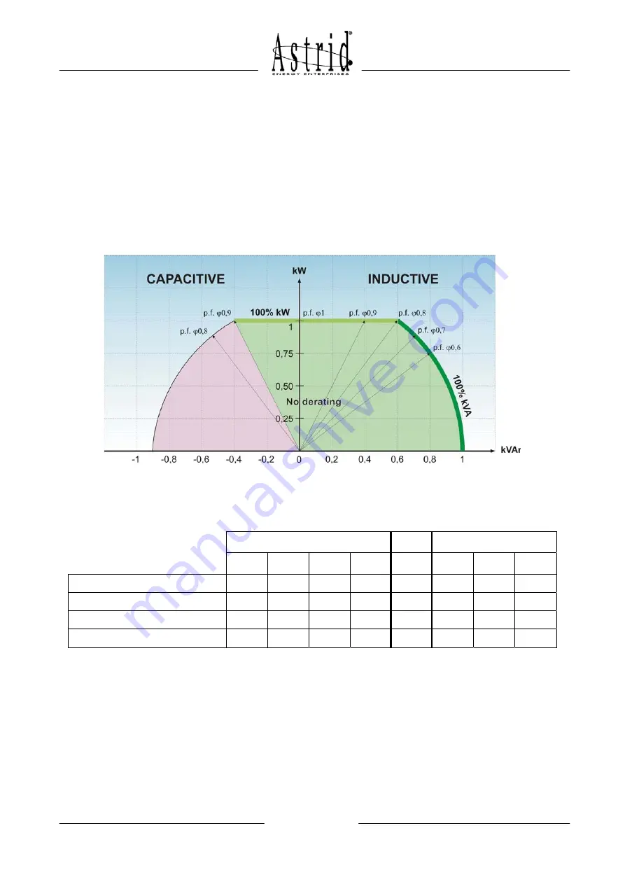
able to supply indifferently inductive or capacitive loads. The maximum apparent power
varies slightly in case the load is highly capacitive (p.f. < 0,9) and a de-rating factor,
according to the picture 5, must be applied. The data “100% kW” indicates the maximum
active power that the UPS can supply to a resistive load (ex: for a 100kVA UPS
Pmax=80kW). The table that follows the diagram shows an example of calculation for a
60kVA UPS.
Picture 5 – Diagram of the power
Example: UPS 60kVA
Pmax = 48kW
cos
ϕ
(capacitive)
cos
ϕ
(inductive)
0,6 0,7 0,8 0,9 1 0,8 0,7 0,6
P / Pmax
1
1
1
0,875
0,75
Max active power (kW)
32 37,3 42,6 48 48 48 42 36
Reactive power (kVar)
42,6 38 32 23 - 36 42,8 48
Apparent power (kVA)
53,3 53,3 53,3 53,3
-
60 60 60
2.2.1 Operation with non-linear load
A non-linear load is characterized by a high peak current versus its RMS value, that in
normal condition would introduce a distortion on the output waveform.
The inverter is provided with an instantaneous voltage correction facility, completely
managed by the microprocessor, that provides to vary the PWM generation according to
the actual output waveform, in order to keep the THD within 5% even with loads having
crest factor equal to 3.


