Chapter 2 Operation
31
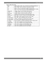
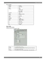
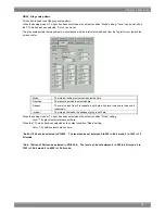
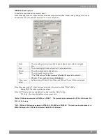
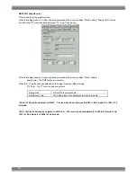
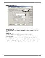
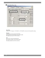
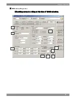
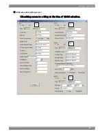
GRAY: Gray scale pattern
This button is used to set the gray scale pattern.
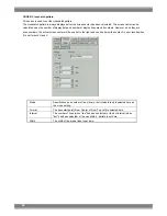
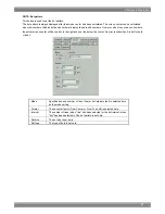
When the analog mode or Tri-Sync has been selected as the output condition "Mode" setting, "Level" can be set; when
the TTL mode has been selected, "Color" can be set.
The gray scale pattern is always drawn in accordance with the interval provided and from the top left corner toward the
screen center.
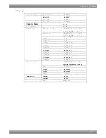
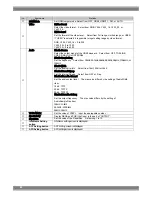
Mode
The interval setting increment is selected here.
Direction
The layout direction is selected here.
Repeat
The color values from 0 to repeat are set here when level values are to be used
repeatedly.
Interval
The interval between the shades of gray is set here.
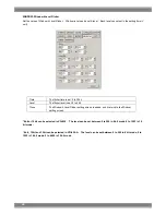
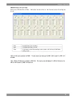
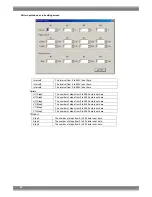
When the analog mode or Tri-Sync has been selected as the output condition "Mode" setting:
Level : The gray display levels are set here.
When the TTL mode has been selected as the output condition "Mode" setting:
Color : The halftone levels are set here.
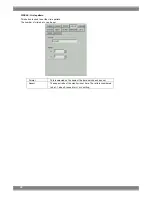
* 8bit or 10bit can be selected in VG-835. The level can be set between 0 to 255 in 8 bit mode, 0 to 1023 in 10
bit mode.
* 8bit , 10bit and 12bit can be selected in VG-835-A. The level can be set between 0 to 255 in 8 bit mode, 0 to
1023 in 10 bit mode, 0 to 4095 in 12 bit mode.
Summary of Contents for SP-8848
Page 1: ...Portable signal generator programming software SP 8848 Instruction Manual Ver 2 6...
Page 2: ......
Page 4: ......
Page 16: ...8...
Page 117: ...Chapter 2 Operation 109 Text data setting screen...
Page 119: ...Chapter 2 Operation 111 V chip setting screen...
Page 122: ...114...
Page 124: ...116...

