118
(4)
Value
0-65535
A value is set only when
Set VCP Feature
has been selected
as the Mode setting.
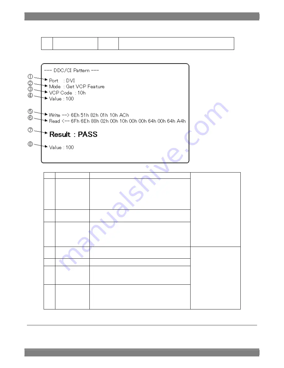
Display example of sent and received data using the DDC-CI setting
①
Port
Output port from which DDC/CI is transferred
②
Mode
DDC/CI transfer mode
Get VCP Feature: The status of the connection
destination is received.
Set VCP Feature: The control commands are sent
to the connection destination.
③
VCP Code
Transfer command (set using the hexadecimal format)
④
Value
(Displayed only when Set VCP Feature has been
selected as the Mode setting.)
Parameter value to be transferred from the generator to
the connection destination
Items to be set by the
generator
⑤
Write
Data sent from the generator
⑥
Read
Data received by the generator
⑦
Result Transfer
result
PASS: Data was transferred successfully.
NG: Transfer failed.
⑧
Value
(Displayed only when Get VCP Feature has been
selected as the Mode setting.)
Parameter value received by the VG-884 from the
connection destination
Items that display the
receiving or sending
results
4.13.7 CEC list
The CEC list display can be selected by pressing the NAME/LIST key while the generator is connected to the display.
Summary of Contents for VG-884
Page 1: ...Portable Video Signal Generator VG 884 Instruction Manual Ver 1 00 ...
Page 2: ......
Page 3: ...Portable Video Signal Generator VG 884 Instruction Manual 2012 7 Ver 1 00 ASTRODESIGN Inc ...
Page 4: ......
Page 16: ...xii ...
Page 26: ...10 ...
Page 58: ...42 ...
Page 93: ...Chapter 4 Selecting and Editing Pattern Data 77 ...
Page 96: ...80 ...
Page 99: ...Chapter 4 Selecting and Editing Pattern Data 83 12BIT 0 4095 ...
Page 108: ...92 0 1 2 3 4 5 6 ...
Page 147: ...Chapter 5 Output Settings 131 MENU Display returns to the initial screen ...
Page 161: ...Chapter 5 Output Settings 145 3 4Kx2K 24Hz SMPTE ...
Page 164: ...148 9 16 9 4 3 center ...
Page 166: ...150 3 AdobeYCC601 4 AdobeRGB ...
Page 170: ...154 6 176 4kHz 7 192kHz ...
Page 177: ...Chapter 5 Output Settings 161 2 12bit ...
Page 183: ...Chapter 5 Output Settings 167 1 Advance Cipher Enhanced Link Verification is not supported ...
Page 206: ...190 9 16 9 4 3 center ...
Page 208: ...192 3 AdobeYCC601 4 AdobeRGB ...
Page 211: ...Chapter 5 Output Settings 195 7 192kHz ...
Page 228: ...212 ...
Page 246: ...230 Teletext waveforms ...
Page 270: ...254 ...
Page 290: ...274 Select EXECUTE using or INC DEC and then press SET to erase the user characters ...
Page 304: ...288 ...
Page 351: ...Carter10 Internal data 335 ...
Page 354: ...338 F0H letters me 1 F1H letters me 2 VESA specifications ...
Page 355: ...Carter10 Internal data 339 ...
Page 356: ...340 F2H Chinese character AI F3H Chinese character BI ...
Page 357: ...Carter10 Internal data 341 ...
Page 358: ...342 F4H Chinese character TAKA F5H Chinese character KIRI ...
Page 359: ...Carter10 Internal data 343 ...
Page 360: ...344 F6H Chinese character KEN F7H Burst ...
Page 361: ...Carter10 Internal data 345 ...
Page 362: ...346 10 4 Character pattern data 5 7 character pattern table 1 of 2 ...
Page 363: ...Carter10 Internal data 347 ...
Page 364: ...348 5 7 character pattern table 2 of 2 ...
Page 365: ...Carter10 Internal data 349 7 9 character pattern table 1 of 2 ...
Page 366: ...350 ...
Page 368: ...352 ...
Page 369: ...Carter10 Internal data 353 16 16 character pattern table 1 of 4 ...
Page 370: ...354 ...
Page 371: ...Carter10 Internal data 355 16 16 character pattern table 2 of 4 ...
Page 372: ...356 ...
Page 373: ...Carter10 Internal data 357 16 16 character pattern table 3 of 4 ...
Page 374: ...358 ...
Page 375: ...Carter10 Internal data 359 16 16 character pattern table 4 of 4 ...
Page 376: ...360 ...
Page 379: ...Chapter10 Internal data 363 Table of TV standard signal timing waveforms 1 of 3 ...
Page 380: ...364 Table of TV standard signal timing waveforms 2 of 3 ...
Page 381: ...Chapter10 Internal data 365 Table of TV standard signal timing waveforms 3 of 3 ...
Page 382: ...366 ...
Page 384: ...368 ...


