background image


8   


If  the  customer  requires  PV  modules  to  be 

distinguished  by  color,  the  outer  packaging  box  shall 

be  marked  accordingly,  and  the  PV  modules  shall  be 

marked  to  prevent  confusion  when  they  are  taken  out 

of the packaging box and stacked up. According to the 

system  design  requirements,  the  color  of  PV  modules 

in the same row or the same array should be the same. 

5


Mechanical installation 

5.1


Environment 


Recommended ambient temperature: -20°C to 50°C; 

extreme  operating  ambient  temperature  for  PV 

modules: -40 °C to 85°C. 


The modules mentioned in this installation manual 

are  only  allowed  to  be  installed  below  2000  m 

above sea level. 


Mechanical  load  on  PV  modules:  under  standard 

installation  conditions,  the  maximum  tested 

snow/wind load is 5400 Pa/2400 Pa and the design 

load  (considering  a  safety  factor  of  1.5  times)  is 

3600Pa/1600Pa.  Refer  to  5.3  for  detailed 

installation and mechanical loads. 


PV  modules  are  strictly  forbidden  to  be  installed 

and  used  in  environments  with  excessive  amounts 

of  hail,  snow,  hurricanes,  sand,  soot,  air  pollution, 

and  etc.  PV  modules  are  strictly  forbidden  to  be 

installed  or  used  in  environments  where  there  are 

strongly  corrosive  substances  (e.g.  salt,  salt  spray, 

brine,  active  chemical  vapors,  acid  rain,  strong 

vapor  confined  environments  or  any  other 

substance that will corrode PV modules and affect 

their safety or performance). 


If  the  PV  modules  will  be  installed  in  special 

environments  such  as  high  temperature  and  high 

humidity 

environments, 

humid 

salt-mist 

environments  (C3+areas  specified  in  ISO  9223), 

marine  and  floating  environments  and  farms,  the 

purchaser  or  user  needs  to  inform  Chint  Solar  in 

advance.  The  types  of  PV  modules,  BOM,  and 

warranty  issues  will  be  decided  by  mutual 

agreement between the parties. 


If  the  above  precautions  are  not  observed,  Chint 

Solar’s warranty will be void. 

5.2


Tilt angle selection 

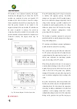
The  tilt  angle  of  a  PV  module  refers  to  the  angle 

between the surface of the PV module and the ground 

surface, as shown in Fig. 1. The power output of a PV 

module is maximized. when it faces the sun directly. 


Fig. 1 Schematic diagram of tilt angle 

For  northern  hemisphere,  PV  modules  should 

preferably  face  south.  For  southern  hemisphere,  PV 

modules  should  preferably  face  north.  For  detailed 

mounting  inclination,  please  follow  local  regulatory 

guidelines  or  the  recommendations  of  an  experienced 

installer.  Chint  Solar  recommends  an  installation  tilt 

angle of no less than 10°, so that when it rains, the dust 

on surface is easily carried away by the rainwater, thus 

reducing  the  number  of  times  of  clean;  at  the  same 

time,  it  helps  the  water  on  the  surface  of  the  PV 

module  to  flow  away,  avoiding  the  long-term 

accumulation  of  large  amounts  of  water  on  the  glass 

surface,  which  can  affect  the  appearance  and 

Summary of Contents for Chint Solar CHSM54N-HC

Page 1: ...1 Crystalline Silicon PV Module Installation Manual...

Page 2: ...1 Transport 6 4 2 Unpack 7 4 3 Stack 7 5 Mechanical installation 8 5 1 Environment 8 5 2 Tilt angle selection 8 5 3 Mounting Guide 9 5 3 1 Bolted mounting 9 5 3 2 Clamped mounting 10 6 Electrical Inst...

Page 3: ...M HC CHSM66N LV HC CHSM60N LV HC CHSM78N LV HC CHSM72N LV HC CHSM54N LV HC CHSM78M LV HC CHSM55M LV HC CHSM50M LV HC CHSM60N BL HC CHSM72N BLH HC CHSM72N BL HC CHSM60N BLH HC CHSM54N BLH HC CHSM54N BL...

Page 4: ...ear safety helmets insulating gloves safety shoes and use insulating tools to avoid the direct contact with a DC voltage of 30V or even higher When installing or operating PV modules on rainy days or...

Page 5: ...time in order to avoid glass damage it is forbidden to apply excessive load or distorted PV modules Do not install or carry PV modules by one person It is forbidden to pick up drag or move PV modules...

Page 6: ...shock protection equipment that meets the requirements When professionals replace or repair PV modules do not damage the surrounding PV modules or their support structures When cleaning PV modules yo...

Page 7: ...r non sharp and stable items to prop up one of the long side enclosure frame and then cut the other side of the frame Two people in turn move and take out the PV modules The whole handling process nee...

Page 8: ...er substance that will corrode PV modules and affect their safety or performance If the PV modules will be installed in special environments such as high temperature and high humidity environments hum...

Page 9: ...odule is not covered by snow In addition it should be ensured that the lowest end of the PV module is not shaded by surrounding trees or other vegetation When the PV module is mounted on a rack parall...

Page 10: ...ring washer or toothed lock washer Finally lock with a stainless steel nut The tightening torque is recommended to be 9 12Nm for M6 bolts and 17 23Nm for M8 bolts Due to the possible difference of bol...

Page 11: ...ipped with grooves compatible with an M8 bolt If the grooves are not provided holes of a suitable diameter may need to be drilled to allow bolts attaching to the rail at the same locations as mentione...

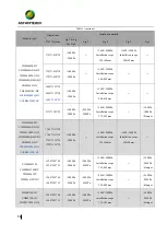
Page 12: ...n method Fig 2 Fig 3 Fig 4 Fig 5 Fig 8 Fig 9 Fig 6 CHSM6610M CHSM6610M HV CHSM6610P CHSM6610P HV CHSM6610M BL 1648 990 35 1648 990 40 5400Pa 2400Pa 5400 2400Pa Installation scope 198 408mm 2400 2400Pa...

Page 13: ...HC 1692 1002 35 5400Pa 2400Pa 5400 2400Pa Installation scope 350 50mm 2400 2400Pa Installation scope 50 200mm 1755 1038 35 1765 1048 35 5400Pa 2400Pa 5400 2400Pa Installation scope 400 50mm 1800 1800P...

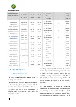
Page 14: ...Pa 2400Pa 5400 2400Pa Installation scope 375 425mm 1800Pa 1800Pa Bumper CHSM54M HC CHSM54M BL HC CHSM54M LV HC CHSM54M BLH HC CHSM54N HC CHSM54N BLH HC CHSM54N BL HC 1708 1133 30 1708 1133 35 1722 113...

Page 15: ...00Pa Installation scope 375 425mm 1800Pa 1800Pa Bumper CHSM78N HC CHSM78N LV HC CHSM78M HC CHSM78M LV HC 2465 1134 35 5400Pa 2400Pa 2400Pa 2400Pa 5400 2400Pa Installation scope 400 450mm 1800Pa 1800Pa...

Page 16: ...capacity of wires and fuse and parameters associated with the output power of PV modules the corresponding short circuit current and open circuit voltage should be applied with a safety factor of 1 2...

Page 17: ...k their structural configuration before proceeding with the connection The number of modules connected in series and parallel should be reasonably designed according to the system configuration PV mod...

Page 18: ...an anodised corrosion resistant aluminum alloy frame as a rigid support To ensure safety and to avoid lightning strikes and electrostatic damage to the PV modules the PV module frame must be earthed T...

Page 19: ...roken module with a new one of the same type in time It is recommended to perform preventive inspection every 6 months and not to replace the components of PV modules without authorization When conduc...

Page 20: ...chain damaging your health and well being When replacing old appliances with new ones the retailer is legally obligated to take back your old appliance for disposals at least free of charge For more...

Page 21: ...ev 1 0 released in June 2018 Rev 1 1 released in July 2020 Rev 1 2 released in October 2021 Rev 1 3 released in Apr 2022 Chint New Energy Technology Co Ltd Add No 1 Jisheng Road Jianshan New Zone Hain...

Page 22: ...45 67 45 86 45 98 46 16 46 37 46 57 46 70 47 01 47 26 47 51 47 76 48 01 48 26 48 51 48 76 Tolerance of Rating Pmax Isc Voc 3 5 3 3 5 3 Over current protection rating A 15 20 15 20 Classification IEC...

Page 23: ...area m 1 63 1 64 1 66 1 63 1 64 1 66 Min creepage distance mm 10 4 10 4 N mber of solar cells 60 60 Cells per bypass diode 20 20 Serial parallel connection of cells S S Module family B Mono c Si cell...

Page 24: ...d Maxim m Power W 275 280 285 290 295 300 305 310 315 320 325 330 335 275 280 285 290 295 300 305 310 315 320 325 330 335 Rated Short Circuit Current A 9 38 9 41 9 46 9 54 9 59 9 68 9 72 9 86 9 98 10...

Page 25: ...6 11 32 11 38 Rated Open Circuit Voltage V 45 08 45 23 45 38 45 53 45 74 45 86 46 04 46 25 46 45 47 15 47 36 47 63 47 87 48 15 48 37 48 55 48 66 48 78 48 87 48 28 48 61 49 05 47 98 48 28 48 58 48 88 4...

Page 26: ...83 39 78 40 08 40 38 37 45 37 69 37 93 38 17 38 41 38 65 38 90 39 14 38 52 38 75 39 01 39 27 39 52 39 78 40 07 40 37 40 23 40 51 40 83 39 78 40 08 40 38 Tolerance of Rating Pmax Isc Voc 3 5 3 3 5 3 Ov...

Page 27: ...0 50 30 45 30 45 61 45 91 46 21 46 52 46 83 47 13 47 44 47 64 47 89 48 18 48 47 48 70 48 98 49 25 49 53 49 80 50 06 50 32 47 73 47 99 48 25 48 50 48 80 49 05 49 35 49 65 49 95 50 25 50 51 48 90 49 10...

Page 28: ...75 39 84 40 11 40 42 40 72 41 03 41 32 41 61 41 88 42 16 42 44 39 80 40 14 40 41 40 75 41 05 41 34 41 64 41 94 42 20 41 10 41 30 41 50 41 70 41 90 Tolerance of Rating Pmax Isc Voc 3 5 3 3 5 3 Over cur...

Page 29: ...II Class II Fire rating Class C Class C Pollution degree I I Dimensions l x w x h mm 2096x1038x35 30 2073x1133x35 2094x1134x35 2384x1303 x35 Module area m 2 18 2 35 2 37 3 11 Min creepage distance mm...

Page 30: ...C xxx mono 120 cells Maxim m System Voltage VDC 1500 1000 1500 1000 Rated Maxim m Power W 390 395 400 405 410 415 435 440 445 450 455 460 465 Rated Short Circuit Current A 13 40 13 52 13 65 13 76 13 8...

Page 31: ...Fire rating Class C Class C Pollution degree I I Dimensions l x w x h mm 2384x1096 x35 2172 x1096 x 35 Module area m 2 61 2 38 Min creepage distance mm 10 4 10 4 Number of solar cells 110 100 Cells pe...

Page 32: ...e rating Class C Class C Pollution degree I I Dimensions l x w x h mm 1986x992x40 45 35 30 2000x992x40 45 35 30 2018x1002x40 45 35 30 2108x1046x40 45 35 30 2108x1048x40 45 35 30 2094 1038x40 45 35 30...

Page 33: ...61730 Class II Class II Fire rating Class C Class C Pollution degree I I Dimensions l x w x h mm 1666x992x35 40 30 1675x992x35 40 30 1692x1002x35 40 30 1768x1046x35 40 30 1765 x1048x35 40 30 1755x1038...

Page 34: ...ype CHSM54M BLH HC xxx CHSM54M BL HC xxx from 390W to 405W is with cell dimension 182mmx91mm Power range of model type CHSM78M HC xxx CHSM78M LV HC xxx from 565W to 605W is with cell dimension 182mmx9...

Page 35: ...Current A 13 54 13 62 13 70 13 78 13 86 13 95 14 03 13 70 13 80 13 90 14 00 Rated Open Circuit Voltage V 54 02 54 22 54 42 54 62 54 82 55 02 55 22 50 25 50 40 50 55 50 70 Tolerance of Rating Pmax Isc...

Page 36: ...20 Cells per bypass diode 36 40 Serial parallel connection of cells SP SP Remark Power range of model type CHSM54N HC xxx CHSM54N LV HC xxx from 405W to 425W is with N type cell dimension 182mmx91mm P...

Page 37: ...ax Isc Voc 3 5 3 Over current protection rating A 25 with junction box CHS2x PV HBE4x CHS3xyz Classification IEC 61730 Class II Fire rating Class C Pollution degree I Dimensions l x w x h mm 1903x1134...

Page 38: ...38 Pmp Ima are measured under STC irradiance 1000 mW cm2 AM 1 5 and cell temperature 25 C...

Reviews: