9
performance of the PV module.
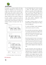
PV modules connected in series should be installed in
the same orientation and angle. Different orientations
and angles may result in different amounts of solar
radiation being received by each module, resulting in
power loss.
5.3
Mounting Guide
PV module mounting system must be composed of
durable,
corrosion-resistant
and
UV-resistant
materials, and it must be inspected and tested by a
third-party
testing
organization
with
static
mechanical analysis capabilities meeting national
and
regional
regulations
or
corresponding
international standards.
The PV module must be securely fastened to the
mounting system. If the PV module is mounted in a
snowy area, the height of the mounting system
should be designed in a way that the lowest end of
the PV module is not covered by snow. In addition,
it should be ensured that the lowest end of the PV
module is not shaded by surrounding trees or other
vegetation.
When the PV module is mounted on a rack parallel
to the roof, the minimum clearance between the PV
module frame and the roof is 10cm, which is
necessary for air circulation to prevent wiring
damage of the PV module.
The PV module frame will suffer thermal
expansion and contraction effect, therefore the
space between two adjacent PV module frames
should be no less than 10mm when mounted.
For detailed installation methods, please refer to the
following specifications:
5.3.1
Bolted mounting
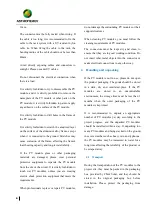
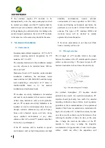
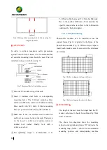
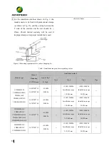
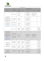
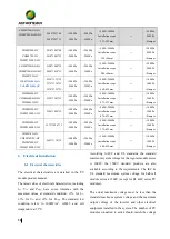
All modules must be securely fastened with at least 4
bolts (As shown in Fig. 2, Fig. 3, Fig. 4 , Fig. 5 and
Fig. 6). The corresponding mechanical loads are
shown in Table 1.
Fig 2. Bolt installation for 54cell
Fig 3. Bolt installation for 60cell
Fig 4. Outer four-hole bolt installation for 72cell
Fig 5. Internal four-hole bolt installation for 72cell


