background image

5

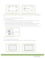
Figure 1.


Bolt positions for the at-minimum four-bolts for a) modules CHSM5409M, CHSM6609M/P, CHSM6610M/P; and b) modules CHSM6611P 

and CHSM6612P. Solid red arrows indicate primary bolt positions; dashed blue arrows indicate positions where bolts can be added for additional 
support.

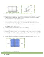
Bolts are inserted as described in the process below (see figure 2).
1.    Place the module on the frame.
2.    Insert four stainless-steel bolts (M6) through the holes (7x11.5mm) in the frame according to figure 1. For maximum  
        security against strong winds and heavy snow, all available mounting holes should be used.
3.     Secure each bolt to the frame with 2 stainless-steel washers, one on each side of the mounting structure; and screw on  
         either a stainless-steel spring washer or a toothed lock washer. Finally, secure with a stainless steel nut (M6).
4.    The torque for tightening the nut and bolts recommended 13Nm when  the property class of bolts and screws is Class 8,8.


Figure 2. Securing the module with bolts.

3.2.2 

Clamping with clamps (aluminum alloy)

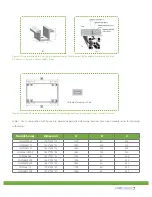
Modules can be laid either across the supporting bars (figure 3a) or parallel to them (figure 3b and figure 3c).


(a)

(b)

(a)

(b)

Summary of Contents for CHSM6610M

Page 1: ...THE POWER OF ASTRONERGY CRYSTALLINE SILICON PV MODULE INSTALLATION GUIDE...

Page 2: ...2 Safety 3 Mechanical Installation 4 Electrical Installation 5 Maintenance and Disposal 1 1 Purpose 1 2 Limitation of Liability 2 1 General Safety 2 2 Installation Safety 3 1 Installation Condition 3...

Page 3: ...n use or maintenance Astronergy reserves the right to change the manual without prior notice 2 Safety 2 1 General Safety 2 1 1 Consult and follow local codes and other applicable laws concerning requi...

Page 4: ...oting the PV system 2 2 11 Follow the safety regulations for any and all other system components including wires connectors charging regulators batteries inverters etc 2 2 12 Do not expose wires to di...

Page 5: ...ng to figure 1 For maximum security against strong winds and heavy snow all available mounting holes should be used 3 Secure each bolt to the frame with 2 stainless steel washers one on each side of t...

Page 6: ...oves holes of a suitable diameter may need to be drilled to allow bolts to be attached to the bars at the same locations as mentioned before 5 Secure each clamp by attaching plain washer spring washer...

Page 7: ...with figure 6 to determine permitted clamping locations for a given module series for clamping with clamps Module Series Dimension A B C CHSM5409M 1200 554 35 1200 50 250 CHSM5611M 1453 808 35 1453 20...

Page 8: ...r of 1 25 when determining component voltage ratings conductor ampacities fuse sizes and size of controls connected to the PV output 4 1 5 Refer to Section 690 8 of the National Electrical Code for an...

Page 9: ...hen through the hole in the aluminum frame 4 2 4 Add the spring washer and nut on the other side of the bolt and tighten to secure all parts The tightening torque should be 210 20 N cm 5 Maintenance 5...

Page 10: ...g Bangkok 10320 Thailand Tel 662 645 4155 Fax 662 245 3185 BRANCH OFFICES Spain Chint Solar Hispania S L Paseo de Gracia 78 2 2A 08008 Barcelona Spain Tel 34 9346 73778 Fax 34 9346 73789 Germany Astro...

Reviews: