6
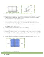
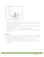
Figure 3. Illustrations of the three different methods for clamping modules onto the frame with aluminum clamps.
Each aluminum mounting clamp comes with an M8 bolt, a plain washer, a spring washer, and an M8 nut. To fasten the module:
1. Lay the module on the two supporting bars (not provided). The bars should be made with stainless material or treated
with an anti-corrosion process (e.g., anodic oxidation treatment).
2. The bar’s top surface contacted with module frame should come with grooves compatible with an M8 bolt.
3. Slide bolts through groove on the supporting bars next to the locations where the 4 clamps are to be fastened.
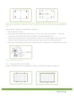
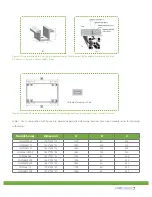
The module may be clamped only in the permitted clamping areas on the long edge of the frame. For exact locations
on the frame refer to figure 6 in conjunction with table 1 below.
4. If the bars do not come with grooves, holes of a suitable diameter may need to be drilled to allow bolts to be attached to
the bars at the same locations as mentioned before.
5. Secure each clamp by attaching plain washer, spring washer, and nut, in that order.
6. The modules may be mounted using clamps designed for solar modules as shown in Figures 3b, the modules must be
supported along the length of the long edge, and should overlap the array rail by 10mm – 14mm as shown in Figures 3d.
7. The modules may be mounted using clamps designed for solar modules as shown in Figures 3c. Note that the clip positions
are important – the clamp centerlines must be between 50mm and 200mm from the end of the module (Note: this method
is not suitable for these two kinds of modules: CHSM6610M/P - 1652*994*35, because their mechanical load could not
pass 5400Pa, but could pass 2400Pa).
8. The torque for tightening the nut and bolts recommended 28Nm when the property class of bolts and screws is Class 8,8.
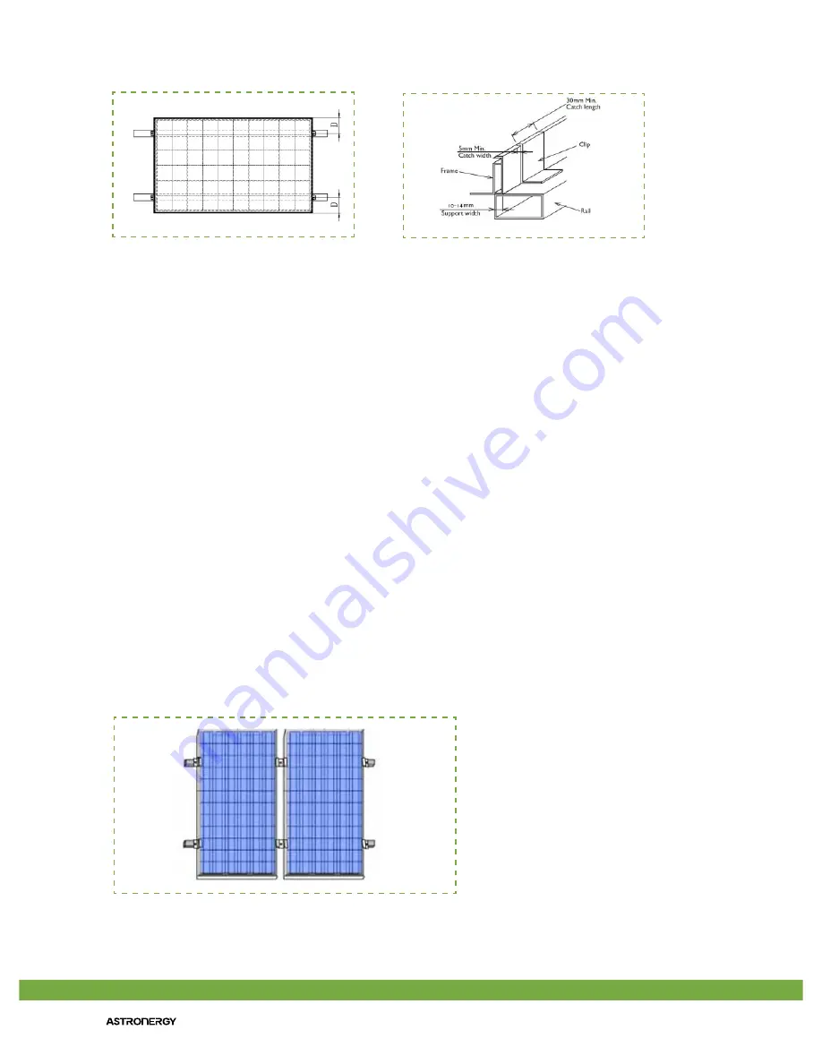
Figure 4. Placement of middle and side clamps on the modules
(c)
(d)
middle
clamps
side
clamps


