background image

7

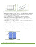
Figure 5. Close-ups of middle (a) and side (b) aluminum clamps. The dimensions for the middle clamps are a ≥ 40 mm, 
b ≥ 26 mm, c = 8 mm, d ≥ 28 mm, and Ø = 9 mm.


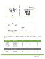
Figure 6. Permitted clamping locations with clamp. For exact dimensions for a given module series, see table 1 (below).

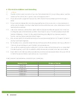
Table 1. Use in conjunction with figure 6 to determine permitted clamping locations for a given module series for clamping 

with clamps.

Module Series

Dimension

A

B

C

CHSM5409M

1200*554*35

1200

50

250

CHSM5611M

1453*808*35

1453

200

150

CHSM5612M

1580*808*35

1580

200

200

CHSM6610PM/P

1652*994*35

1652

200

210

CHSM6606P

1020*994*45

1020

50

205

CHSM6609M/P

1494*994*45

1494

50

320

CHSM6610M/P

1652*994*45

1652

50

360

CHSM6611P

1798*994*50

1798

60

400

CHSM6612M/P

1956*994*50

1956

60

440

 Variable clamping range

(b)

(a)

Summary of Contents for CHSM6610M

Page 1: ...THE POWER OF ASTRONERGY CRYSTALLINE SILICON PV MODULE INSTALLATION GUIDE...

Page 2: ...2 Safety 3 Mechanical Installation 4 Electrical Installation 5 Maintenance and Disposal 1 1 Purpose 1 2 Limitation of Liability 2 1 General Safety 2 2 Installation Safety 3 1 Installation Condition 3...

Page 3: ...n use or maintenance Astronergy reserves the right to change the manual without prior notice 2 Safety 2 1 General Safety 2 1 1 Consult and follow local codes and other applicable laws concerning requi...

Page 4: ...oting the PV system 2 2 11 Follow the safety regulations for any and all other system components including wires connectors charging regulators batteries inverters etc 2 2 12 Do not expose wires to di...

Page 5: ...ng to figure 1 For maximum security against strong winds and heavy snow all available mounting holes should be used 3 Secure each bolt to the frame with 2 stainless steel washers one on each side of t...

Page 6: ...oves holes of a suitable diameter may need to be drilled to allow bolts to be attached to the bars at the same locations as mentioned before 5 Secure each clamp by attaching plain washer spring washer...

Page 7: ...with figure 6 to determine permitted clamping locations for a given module series for clamping with clamps Module Series Dimension A B C CHSM5409M 1200 554 35 1200 50 250 CHSM5611M 1453 808 35 1453 20...

Page 8: ...r of 1 25 when determining component voltage ratings conductor ampacities fuse sizes and size of controls connected to the PV output 4 1 5 Refer to Section 690 8 of the National Electrical Code for an...

Page 9: ...hen through the hole in the aluminum frame 4 2 4 Add the spring washer and nut on the other side of the bolt and tighten to secure all parts The tightening torque should be 210 20 N cm 5 Maintenance 5...

Page 10: ...g Bangkok 10320 Thailand Tel 662 645 4155 Fax 662 245 3185 BRANCH OFFICES Spain Chint Solar Hispania S L Paseo de Gracia 78 2 2A 08008 Barcelona Spain Tel 34 9346 73778 Fax 34 9346 73789 Germany Astro...

Reviews: