Publication No. 981049 Rev. B
PXIe-3352 User Manual
Astronics Test Systems
Software Operation 4-5
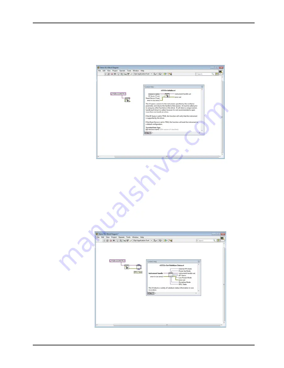
A rudimentary VI block diagram with just the ri3352e Intiialize.vi is shown below.
This VI shows that the instrument descriptor has been selected and wired into the
VI.
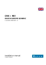
The next step is to add the various driver VIs that provide the information you need
in your application. The image below demonstrates that a second VI has been
added to the diagram. This VI, “ri3352e Get Rubidium Status.vi”, retrieves status
information from the Rubidium module in the 3352e.
One requirement for using the driver is to wire the “instrument handle out” output
from one VI to the “instrument handle” input on the next VI. A second requirement
for using the driver is to wire the “error out” output from one VI to the “error in”
input of the next VI. These two connections are shown in the diagram below:


![Navig[8]r NAVBIKE-GPS User Manual preview](http://thumbs.mh-extra.com/thumbs/navig-8-r/navbike-gps/navbike-gps_user-manual_3574097-01.webp)


