background image


804 S. Northpoint Blvd. | Waukegan, IL 60085


astronics.com


+1.847.244.4500


E71-314  
Sierra™ 
User’s Manual 


THIS DOCUMENT IS THE SOLE PROPERTY OF ASTRONICS CONNECTIVITY SYSTEMS & CERTIFICATION (“ASTRONICS CSC”) AND SHALL 
NOT BE REPRODUCED, COPIED OR ISSUED AS THE BASIS OF MAINTENANCE OR SALE OF APPARATUS WIHTOUT PERMISSION OF 
ASTRONICS CSC. 

Astronics CSC 
Inflight Entertainment and Connectivity Systems


THIS DOCUMENT HAS BEEN ELECTRONICALLY SIGNED IN ASTRONICS CSC’S PLM

SYSTEM. ALL ELECTRONIC SIGNATURES ARE ON FILE IN THE PLM SYSTEM AND ARE

FULLY AUDITABLE.

Document Control RELEASED

Summary of Contents for Sierra E71-314

Page 1: ...TRONICS CSC AND SHALL NOT BE REPRODUCED COPIED OR ISSUED AS THE BASIS OF MAINTENANCE OR SALE OF APPARATUS WIHTOUT PERMISSION OF ASTRONICS CSC Astronics CSC Inflight Entertainment and Connectivity Systems THIS DOCUMENT HAS BEEN ELECTRONICALLY SIGNED IN ASTRONICS CSC S PLM SYSTEM ALL ELECTRONIC SIGNATURES ARE ON FILE IN THE PLM SYSTEM AND ARE FULLY AUDITABLE Document Control RELEASED ...
Page 2: ...ndustry Canada licence exempt RSS standard s Operation is subject to the following two conditions 1 this device may not cause interference and 2 this device must accept any interference including interference that may cause undesired operation of the device Le présent appareil est conforme aux CNR d Industrie Canada applicables aux appareils radio exempts de licence L exploitation est autorisée au...

Page 3: ...erminal Communication Settings 20 5 2 SSH 21 5 3 SSID 21 5 4 WAP Configuration 22 6 Connecting using Aruba s Web based GUI 23 7 WLAN Setup 30 8 User Interface 36 8 1 Switch and Display Panel 36 8 2 Battery Status Indicator 38 8 3 Cellular Mode Button 38 8 4 Battery Door 38 9 Performance Data 43 9 1 Aruba Wi Fi Characteristics 43 9 2 Country Codes 45 10 Technical Data 47 10 1 Electrical and Environ...

Page 4: ...ation 6 Table 1 2 Aruba Support Documentation 6 Table 1 3 Industry Standards 7 Table 3 1 Sierra Kit Specific Drawing Information 15 Table 3 2 Sierra Orderable Part Numbers 18 Table 5 1 Com Port Settings 20 Table 8 1 Switch and Display Panel Nomenclature and Function 36 Table 9 1 Radio Characteristics 43 Table 9 2 RF Performance Table 44 Table 9 3 Country Codes 45 Table 10 1 Engineering Test Matrix...

Page 5: ...ted Access Point 27 Figure 6 8 Radio Specific Details 28 Figure 6 9 Clients Section 28 Figure 6 10 Client Details 29 Figure 7 1 The Four Stages to Creating an SSID 30 Figure 7 2 The WLAN Settings Tab of the New WLAN Dialog Box 31 Figure 7 3 The VLAN Tab of the New WLAN Dialog Box 32 Figure 7 4 Configuring an External RADIUS Server 33 Figure 7 5 Configuring Firewall Rules 34 Figure 7 6 External Cap...

Page 6: ...emovable SSD E71 319 01 OL Outline Drawing Assembly Sierra Base Unit E54 576 XX OL Outline Drawing Assembly Removable SSD PS E71 314 Product Specification Sierra 44 20 45 Component Maintenance Manual CMM Sierra ATP E71 314 Acceptance Test Procedure ATP Sierra FMEA E71 314 Failure Modes and Effects Analysis FMEA Sierra See Table 3 1 for kit specific OL drawings Sierra ships with Aruba Instant firmw...

Page 7: ...mum to reduce interference to satellites 1 3 Warranty The Sierra is warranted against defects in materials and workmanship for the warranty period from the date of shipment The warranty does not apply to defects resulting from improper or inadequate maintenance of handling by the buyer unauthorized modification or misuse operation outside of the product s environmental specification of improper in...

Page 8: ...oling in temperatures from 0 C to 50 C To prevent overheating be sure there is adequate air flow around the device and that the heat dissipation holes are not blocked A minimum airgap of 1 should be maintained during operation Please observe all specified dimensions required for mounting included in the kit specific Outline Drawing listed in Table 3 1 3 Sierra has been designed to withstand the me...

Page 9: ...ns may cause harmful interference to radio communications However there is no guarantee that interference will not occur in a particular installation If this equipment does cause harmful interference to radio or television reception which can be determined by turning the equipment off and on the user is encouraged to try to correct the interference by one or more of the following measures Re orien...

Page 10: ...ng interference that may cause undesired operation of the device Cet appareil est conforme à la norme ISED RSS GEN et RSS 247 Son fonctionnement est soumis aux deux conditions suivantes 1 cet appareil ne doit pas provoquer d interférences et 2 cet appareil doit accepter toute interférence y compris les interférences pouvant entraîner un fonctionnement indésirable de l appareil Under Industry Canad...

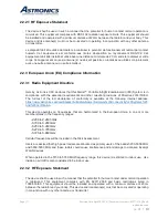
Page 11: ...nts and other relevant provisions of Directive 2014 53 EU The full text of the EU declaration of conformity is available at the following internet address https www astronics com certificates subsidiaryName Astronics 20Connectivity 20Systems 20 And 20Certification This device operates on frequencies that are harmonized in the European Union in one or more member states in the frequency ranges 2 40...

Page 12: ...Chemicals REACH per the EU REACH level 201 Substances of Very High Concern SVHC list released 01 08 2020 The list of controlled substances is available at https echa europa eu candidate list table 2 3 Battery Safety The Sierra holds two rechargeable Lithium Ion battery modules which are to be sourced directly from the battery manufacturer or their distribution centers Each battery module is contro...

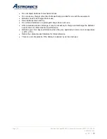
Page 13: ...eep batteries clean and dry Do not leave batteries on a prolonged charge when not in use After extended periods of storage it may be necessary to charge and discharge the batteries several times to obtain maximum performance Batteries give their best performance when they are operated at normal room temperature 20 C 5 C Retain the original product literature for future reference There is a risk of...

Page 14: ...start your streaming and content management application High capacity SSD storage ensures that you can provide ample content for streaming to passenger devices This unit is identified as Astronics CSC P N E71 314 XXX and is branded as SierraTM Note The XXX is a generic placeholder representation of possible variants 3 1 2 Part Number Structure A Sierra kit is comprised of the assembly of the follo...

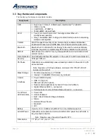
Page 15: ...el AP 303 has been ruggedized and repackaged to meet the operational requirements of commercial aircraft environment The Sierra feature set includes Utilizes a commercial dual band 2 4GHz 5GHz 802 11ac Wave 2 Access Point A dedicated 802 11ac bgn radio 2 4 GHz 5 GHz for networking between multiple Sierra units Dual hot swappable batteries for over 12 hours of video streaming content Up to 2 TB of ...

Page 16: ...ellular modem control Decompression Automatically disables IFE systems in the event of a cabin decompression Security TPM per TPM 2 0 PA Pause Optionally can automatically pause streaming content in the event of a PA announcement Note Requires a PA Pause Module Astronics CSC P N E71 500 01 installed in the aircraft Mass Storage Front Removable Up to 2 TB SSD Internal 16 GB eMMC flash memory on boa...

Page 17: ...pport of other Linux systems available upon request Figure 3 1 shows the Sierra System Block Diagram CPU 4G LTE Cellular Modem SIM Front Panel Maintenance Wi Fi BLE Cell Dis Auto ADS B Recv r USB A USB C Access Point 802 11ac g b n Pwr SW ON OFF RSSD Batt 1 Batt 2 Ext DIN Pwr Connector Front Panel Rear Panel Battery Status SW LEDs and Switch Cell Dis Auto Rear Pnl Ethernet RJ45 µHDMI LED Status Ai...

Page 18: ...Assembly 3 E54 576 XX RSSD Module 4 AHM250PS19 External Power Module with Cable 5 E71 500 01 PA Pause Assembly 6 RRC2054 2 Li Ion Battery purchase directly from RRC Power Solutions 7 E54 577 SSD Block Plate Kit Notes See Table 3 1 for kit specific part numbers Items 2 3 and 4 are included in the Sierra Kit Item 1 P N E71 314 XXX The wall plug interface cable is not included in Item 4 Installation ...

Page 19: ...wer Solutions P N RRC2054 2 are required to power the Sierra Alternatively Sierra can be powered via the aircraft 28VDC power bus with the appropriate STC Refer to Figure 4 1 Figure 4 1 Power Source Once power is connected via batteries or external power source turn the POWER switch to ON position as shown Figure 4 2 Power On Off Switch and Power Indicator ...

Page 20: ...cated behind the battery door as shown in Figure 5 1 There is also an internal console for the cell modem when enabled Use these settings to connect to the consoles Figure 5 1 USB C connection Use these settings to connect to the consoles Table 5 1 Com Port Settings Port Baud Rate Data Bits Parity Stop Bits Flow Control CPU 115200 8 bit none 1 bit none WAP 9600 8 bit none 1 bit none Cell Modem 960...

Page 21: ... allow access to the system from your development network You can ssh into the unit using the Sierra username and password User sierra Password sierra Figure 5 2 Ethernet Port 5 3 SSID Sierra comes configured with the following ATP SSIDs where xxxxxx is replaced with the unit s serial number The password for both is 12345678 xxxxxxw2p4ghz xxxxxxw5ghz ...

Page 22: ...e cfg system config reload this command restarts the WAP To maximize video streaming performance the following settings have been included in the default configuration file var lib tftpboot SierraBlackLabel cfg Wide channel bands are enabled but channel width has been limited to 40MHz This helps clients get on and off the air more quickly Minimum transmit rates have been set to 12 Mbps This preven...

Page 23: ...The web interface main GUI page is broken up into three vertical bands A B C Vertical bands A Virtual Controller The top band contains the Virtual Controller settings these are the global settings B System Components This band contains the system components of the wireless network C Information This band displays information for the currently selected system component The main GUI page is broken u...

Page 24: ...ate April 30 2020 Document Number UM E71 314 Rev B astronics com Clicking on the one of the Blue text items or Green icons will display details of that item Figure 6 2 The Six Sections of the Aruba Instant Main GUI Page ...

Page 25: ...Aruba Username and Password The default system username and password are admin admin It is recommended that these be changed The system username and password can be changed from the Admin tab of the System dialog box as show in Figure 6 3 Figure 6 3 System Username and Password Dialog Box ...

Page 26: ...ue SSID names will show additional details in the Information band The Info section on the left side displays the general settings for the selected network The RF Dashboard section displays a list of any clients experiencing signal or speed issues Clicking on the speed icon brings up a popup window with further details as shown in Figure 6 5 Figure 6 4 Additional Network Information Figure 6 5 Sig...

Page 27: ...e Information band as shown on Figure 6 7 On the left side of the Information section are the operating details along with an RF Dashboard On the right side of the Information band is the Overview section with monitoring graphs On the right side of the Overview title bar we see the Blue selectable text Radio 1 2 4 GHz and Radio 2 5 GHz Selecting one of these text items will display radio specific ...

Page 28: ... with the wireless networks In the Clients section you can see the operating system and wireless capabilities of the devices and also see which wireless network the clients are associated with Figure 6 9 shows the details of the Clients section You can click on a client s name to display the details for that client in the Information band as shown in Figure 6 10 Figure 6 9 Clients Section ...

Page 29: ...Page 29 Revision Date April 30 2020 Document Number UM E71 314 Rev B astronics com Figure 6 10 Client Details ...

Page 30: ...ption will lead you to Captive Portal authentication 2 Configure the Vlan and client IP assignment 3 The security stage depends on your wireless LAN setting selections Enterprise will give you 802 1x selections personal will give you PSK or WEP selections If you select guest you will receive captive portal options 4 The last stage is the settings for the firewall with the user rights These stages ...

Page 31: ...unch the WLAN Wizard by selecting New from the Networks section on the main GUI page This will bring up the WLAN Settings tab of the New WLAN dialog box The WLAN Settings tab is where you select the type of SSID you want to create and name the SSID as shown below in Figure 7 2 Figure 7 2 The WLAN Settings Tab of the New WLAN Dialog Box ...

Page 32: ...WLAN Dialog Box The two client IP assignment options are virtual controller Managed and Network assigned Virtual Controller Managed The client will associate and authenticate to the access point The access point will act as a relay agent to the virtual controller and the virtual controller will provide and act as the DHCP server The Access Points will be providing DHCP for any wireless clients tha...

Page 33: ... on the LAN The APs will bridge the client traffic onto the wire without manipulating or modifying the packets The AP will bridge the client traffic onto the wire The AP turns the wireless frame into an Ethernet frame Step 3 The Security tab is where you set the security level There are three levels Open Personal and Enterprise Selecting the Enterprise level allows you to configure an external RAD...

Page 34: ...ept to the DNS server with the IP address of 192 168 10 1 Figure 7 5 Configuring Firewall Rules Refer to the Aruba Instant Users Guide for additional information on the IAP GUI Captive Portal SSID The following is to create a Captive Portal SSID for your guests In the WLAN Settings tab select the Guest option In the VLAN tab select Network Assigned for Client IP Assignment and Default for Client V...

Page 35: ...tab configure the following Network Based Access Rules o Allow HTTP to a specific server 192 168 1 1 o Allow HTTPS to a specific server 192 168 1 1 o Deny any to any Place the following lines in the body of your index html file which will automatically authenticate your guests form input type hidden id authtext value Guest_Authenticated form ...

Page 36: ...nnotated illustration of the front panel Switch and Display Panel Figure 8 1 Switch and Display Panel Table 8 1 lists the function of the front panel Switch and Display Panel Table 8 1 Switch and Display Panel Nomenclature and Function Switch LED Function Power Switch Power On Off Unit ON Off LED Illuminates when power is applied Blinks while system is booting up External Power LED Illuminates whe...

Page 37: ...e meaning and operation Cellular Mode Button A momentary press cycles through each cell modem mode of operation Cellular Mode LED Icons Displays the cell modem mode of operation when the Cellular Mode button is pressed Illuminates when the cellular modem is ON Illuminates when the cellular modem is in Auto mode Illuminates when the cellular modem is Off Bluetooth Status LED Illuminates when Blueto...

Page 38: ...e of Charge Indicator 8 3 Cellular Mode Button Both the main and diversity antennas are integrated under the radome of the unit The modem is typically turned off when the aircraft is airborne both from an operational standpoint and to preserve battery power Sierra is designed to accept aircraft position and or acceleration data to determine if the aircraft is in motion and automatically control th...

Page 39: ... astronics com Figure 8 3 Battery Door Sierra includes the following features behind the battery door Removable Solid State Drive 1TB m 2 SATA default Micro HDMI port USB C for serial console access to the CPU and access point USB 3 0 port SIM card slot Two battery bays ...

Page 40: ...Page 40 Revision Date April 30 2020 Document Number UM E71 314 Rev B astronics com Figure 8 4 Hardware Interface behind the battery door ...

Page 41: ...Page 41 Revision Date April 30 2020 Document Number UM E71 314 Rev B astronics com 8 4 1 SSD Removal Instructions Figure 8 5 Removable SSD Ejection Instructions ...

Page 42: ... Revision Date April 30 2020 Document Number UM E71 314 Rev B astronics com Note The SSD Block Plate is intended as a theft deterrent device Usage is optional Figure 8 6 Removable SSD Installation Instructions ...

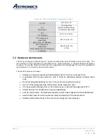
Page 43: ...increments of 0 5 dBm Maximum Available Transmit Power Maximum aggregate conducted total transmit power limited by local regulatory requirements 2 4GHz band 21 dBm 18 dBm per chain 5 GHz band 21 dBm 18 dBm per chain Note conducted transmit power levels exclude antenna gain For total EIRP transmit power add antenna gain correlation gain Supported data rates Mbps 802 11b 1 2 5 5 11 802 11a g 6 9 12 ...

Page 44: ...HT40 2 4GHz MCS0 8 18 0 87 0 MCS7 15 14 0 68 0 802 11a 5GHz 6 Mbps 18 0 90 0 54 Mbps 16 0 73 0 802 11n HT20 5GHz MCS0 8 18 0 90 0 MCS7 15 14 0 71 0 802 11n HT40 5GHz MCS0 8 18 0 87 0 MCS7 15 14 0 68 0 802 11ac VHT20 5GHz MCS0 18 0 90 0 MCS9 12 0 67 0 802 11ac VHT40 5GHz MCS0 18 0 87 0 MCS9 12 0 62 0 802 11ac VHT80 5GHz MCS0 18 0 84 0 MCS9 12 0 59 0 Note Table shows the maximum hardware capabilitie...

Page 45: ...y GG Paraguay PY Armenia AM Haiti HT Peru PE Aruba AW Honduras HN Philippines PH Australia AU Hong Kong HK Poland PL Austria AT Hungary HU Portugal PT Azerbaijan AZ Iceland IS Puerto Rico PR Bahamas BS India IN Qatar QA Bahrain BH Indonesia ID Republic of Korea South Korea KR Bangladesh BD Iran IR Reunion RE Barbados BB Iraq IQ Romania RO Belarus BY Ireland IE Russia RU Belgium BE Islamic Republic...

Page 46: ...Taiwan TW Denmark DK Marshall Islands MH Thailand TH Dominican Republic DO Martinique MQ Trinidad and Tobago TT Ecuador EC Mauritania MR Tunisia TN Egypt EG Mauritius MU Turkey TR El Salvador SV Mayotte YT Uganda UG Estonia EE Mexico MX Ukraine UA Ethiopia ET Monaco MX United Arab Emirates AE Faroe Islands FO Mongolia MC United Kingdom GB Federated States of Micronesia FM Montenegro ME United Stat...

Page 47: ...gh Temperature Test4 DO 160G 4 5 4 A1 Yes Altitude DO 160G 4 6 1 A1 Yes Decompression DO 160G 4 6 2 A Yes Temperature Variation1 5 DO 160G 5 3 1 B Yes Humidity DO 160G 6 3 1 A Yes Operational Shock DO 160G 7 2 1 A Yes Vibration Random DO 160G 8 S Curve B2 Yes Electrostatic Discharge ESD IEC 61000 4 2 Methods Yes Fire Flammability DO 160G 26 C Yes Notes 1 All temperature testing was performed with ...

Page 48: ...ra s metal components include a proper finish to offer maintenance free service over the life of the Sierra The Sierra s internal chassis circuit cards wiring and cabling and other major components are mounted and secured to provide maximum protection against imposed shock and vibration 10 2 1 Top View Figure 10 1 Sierra Top View ...

Page 49: ...Page 49 Revision Date April 30 2020 Document Number UM E71 314 Rev B astronics com 10 2 2 I O Front View Figure 10 2 Sierra I O Front View 10 2 3 Side View Figure 10 3 Sierra Side View ...

Page 50: ...Page 50 Revision Date April 30 2020 Document Number UM E71 314 Rev B astronics com 10 2 4 Rear View Figure 10 4 Sierra Rear View 10 2 5 Bottom View Figure 10 5 Sierra Bottom View ...

Page 51: ...rials used in the Sierra have been selected in accordance with the appropriate flammability requirements of Code of Federal Regulations FAR 25 853a 10 2 9 Weight The Sierra weighs 7 3 lbs which includes a full complement of two 2 Li ion battery modules 10 2 10 Cooling Characteristics The Sierra is designed with passive cooling Battery Powered Power Consumption 15 76W nominal 17 65W max Current Dra...

Page 52: ...actured from materials that do not interfere with the operation of the unit s antennas Transportable enclosures such as bags should include spacers to ensure these minimum air gaps are maintained at all times The air gaps listed above represent minimum required distances between the Sierra s surfaces and a hypothetical enclosure to ensure continued operation without overheating Additional consider...

Page 53: ...30V 3A both to protect against over current conditions The Sierra is also be equipped with a temperature sensor Texas Instruments P N LM75BIMM 3 NOPB that can monitor the unit s internal temperature and be configured in software to inhibit operation in over temperature and under temperature conditions Furthermore Sierra is equipped with two 2 optional Lithium Ion rechargeable Smart Battery Packs w...

Page 54: ...t exceed 15 minutes which entails replacement of the Sierra from its mounting points and disconnection of its electrical connectors 11 4 Failure Detection and Fault Isolation LED indicators located on the system enclosure provide functional status of the Sierra 11 5 Production Testing Production units are subjected to Environmental Stress Screening ESS and a production Acceptance Test Procedure AT...

Page 55: ...ly by Astronics CSC Astronics CSC cannot be held responsible for any loss or damage caused to the equipment received without an RMA number The Buyer accepts responsibility for all freight charges for the return of goods to the Astronic CSC designated facility Astronics CSC will pay return freight charges back to the Buyer s location in the event that the equipment is repaired or replaced within th...

Page 56: ... Level Description of Change Written By Approved By 01 28 2020 A Initial Release Mike O Connor Chris Hinojosa 04 30 2020 B Section 2 2 Updated Wi Fi Transceiver FCC ID Section 2 2 3 1 Updated the EU declaration of conformity URL Added a statement regarding restriction to indoor use Volodya Vandakurov Mike O Connor ...

Reviews: