Chapter 4: Motherboard Information
4-12
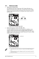
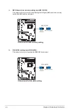
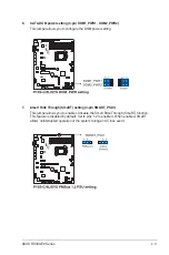
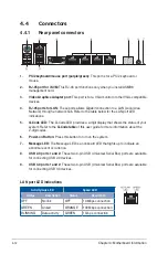
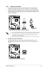
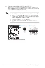
4.4 Connectors
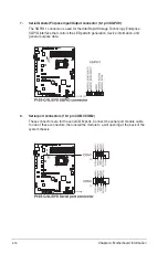
4.4.1
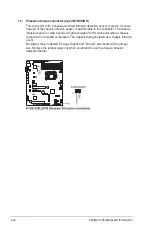
Rear panel connectors
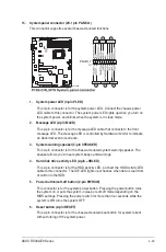
1.
PS/2 keyboard/mouse port (purple/green):
This port is for a PS/2 keyboard or
mouse.
2.
RJ-45 port for iKVM:
This RJ-45 port functions only when you install ASMB8
management card.
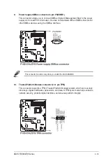
3.
Video Graphics Adapter port:
This port is for a VGA monitor or other VGA-compatible
devices.
4.
RJ-45 ports for LAN:
These ports allows Gigabit connection to a LAN (Local Area
Network) through a network hub. Refer to the table below for the LAN port LED
indications.
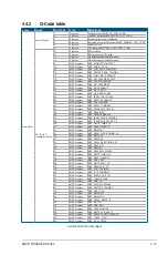
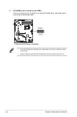
5.
Q-Code LED:
The Q-Code LED provides a 2-digit display that shows the status of your
system. Refer to the
Q-Code table
of this user guide for more information about the
2-digit codes.
6.
Power-on Button:
Press this button to turn on the system.
7.
Message LED:
The Message LED is an onboard LED that lights up to indicate an
abnormal event occurrence.
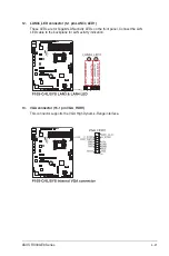
8.
USB 2.0 ports 1 and 2:
These two 4-pin USB (Universal Serial Bus) ports are available
for connecting USB 2.0 devices.
9.
USB 3.0 ports 1 and 2:
These two 4-pin USB (Universal Serial Bus) ports are available
for connecting USB 3.0 devices.
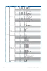
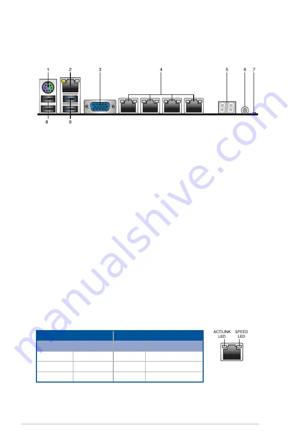
LAN port LED indications
Activity/Link LED
Speed LED
Status
Description
Status
Description
OFF
No link
OFF
10 Mbps connection
GREEN
Linked
ORANGE
100 Mbps connection
BLINKING
Data activity
GREEN
1 Gbps connection
Summary of Contents for 90SV038A-M34CE0
Page 1: ...1U Rackmount Server RS300 E9 PS4 RS300 E9 RS4 User Guide ...
Page 22: ...Chapter 1 Product Introduction 1 10 ...
Page 48: ...Chapter 2 Hardware Information 2 26 ...
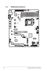
Page 54: ...Chapter 4 Motherboard Information 4 2 4 1 Motherboard layout ...
Page 97: ...5 19 ASUS RS300 E9 Series Intel Server Platform Services Intel TXT Information ...
Page 146: ...6 18 Chapter 6 RAID Configuration ...
Page 157: ...ASUS RS300 E9 Series 7 11 8 Press Restart Now to complete the setup process ...
Page 163: ...Appendix A Appendix ...
Page 164: ...A 2 Appendix P10S C 4L SYS block diagram ...
Page 168: ...A 6 Appendix ...


