Chapter 4: Motherboard Information
4-24
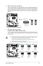
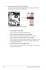
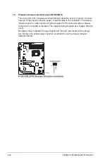
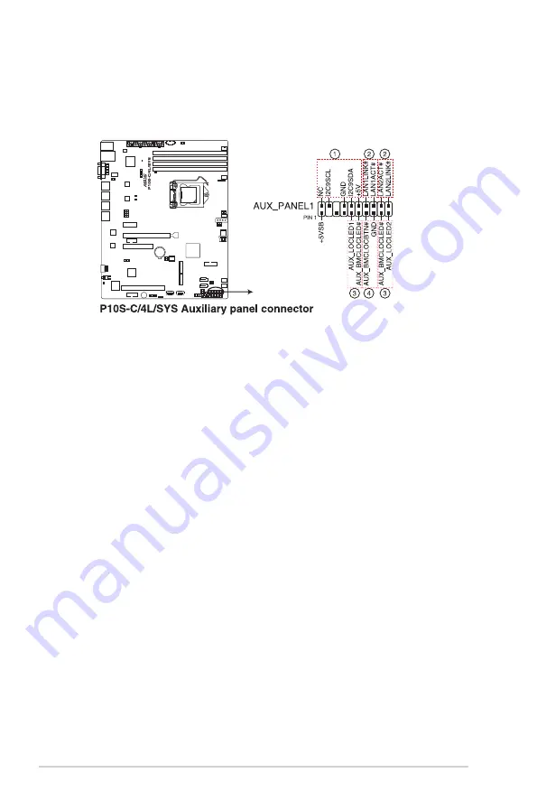
16. Auxiliary panel connector (20-2 pin AUX_PANEL1)
This connector is for additional front panel features including front panel SMB, locator
LED and switch, chassis intrusion, and LAN LEDs.
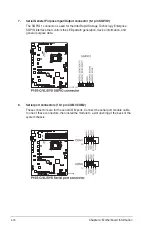
1. Front panel SMB (6-1 pin FPSMB)
These connectors are for the front panel SMBus cable.
2. LAN activity LED (2-pin LAN1LINK and 2-pin LAN2LINK)
These connectors are for Gigabit LAN activity LEDs on the front panel.
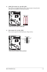
3. Locator LED (2-pin AUX_LOCLED1 and 2-pin AUX_LOCLED2)
These connectors are for the locator LED1 and LED2 on the front panel. Connect
the Locator LED cables to these 2-pin connectors. The LEDs will light up when
the Locator button is pressed.
4. Locator Button/Switch (2-pin AUX_BMCLOCBTN)
These connectors are for the locator button on the front panel. This button queries
the state of the system locator.
Summary of Contents for 90SV038A-M34CE0
Page 1: ...1U Rackmount Server RS300 E9 PS4 RS300 E9 RS4 User Guide ...
Page 22: ...Chapter 1 Product Introduction 1 10 ...
Page 48: ...Chapter 2 Hardware Information 2 26 ...
Page 54: ...Chapter 4 Motherboard Information 4 2 4 1 Motherboard layout ...
Page 97: ...5 19 ASUS RS300 E9 Series Intel Server Platform Services Intel TXT Information ...
Page 146: ...6 18 Chapter 6 RAID Configuration ...
Page 157: ...ASUS RS300 E9 Series 7 11 8 Press Restart Now to complete the setup process ...
Page 163: ...Appendix A Appendix ...
Page 164: ...A 2 Appendix P10S C 4L SYS block diagram ...
Page 168: ...A 6 Appendix ...


