2-13
ASUS RS300-E9 Series
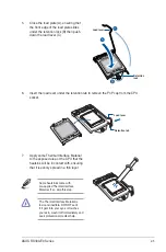
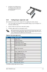
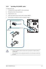
5.
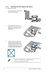
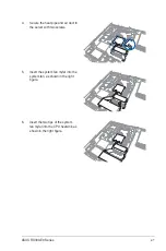
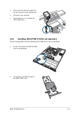
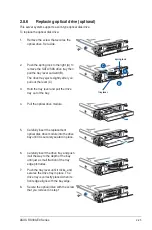
Install the riser card bracket and
PCI Express card assembly back
into the PCI Express x16 slot on
the motherboard.
3
4
2
1
5
Q-Code
1
Q-Code
1
Standard Interrupt assignments
* These IRQs are usually available for ISA or PCI devices.
IRQ
Priority Standard function
0
1
System Timer
1
2
Keyboard Controller
2
-
Programmable Interrupt
3*
11
Communications Port (COM2)
4*
12
Communications Port (COM1)
5*
13
--
6
14
Floppy Disk Controller
7*
15
--
8
3
System CMOS/Real Time Clock
9*
4
ACPI Mode when used
10*
5
IRQ Holder for PCI Steering
11*
6
IRQ Holder for PCI Steering
12*
7
PS/2 Compatible Mouse Port
13
8
Numeric Data Processor
14*
9
Primary IDE Channel
15*
10
Secondary IDE Channel
2.5.2
Configuring an expansion card
After installing the expansion card, configure the it by adjusting the software settings.
1.
Turn on the system and change the necessary BIOS settings, if any. See Chapter 5 for
information on BIOS setup.
2.
Assign an IRQ to the card. Refer to the following tables.
3.
Install the software drivers for the expansion card.
When using PCI cards on shared slots, ensure that the drivers support “Share IRQ” or that
the cards do not need IRQ assignments. Otherwise, conflicts will arise between the two PCI
groups, making the system unstable and the card inoperable.
Summary of Contents for 90SV038A-M34CE0
Page 1: ...1U Rackmount Server RS300 E9 PS4 RS300 E9 RS4 User Guide ...
Page 22: ...Chapter 1 Product Introduction 1 10 ...
Page 48: ...Chapter 2 Hardware Information 2 26 ...
Page 54: ...Chapter 4 Motherboard Information 4 2 4 1 Motherboard layout ...
Page 97: ...5 19 ASUS RS300 E9 Series Intel Server Platform Services Intel TXT Information ...
Page 146: ...6 18 Chapter 6 RAID Configuration ...
Page 157: ...ASUS RS300 E9 Series 7 11 8 Press Restart Now to complete the setup process ...
Page 163: ...Appendix A Appendix ...
Page 164: ...A 2 Appendix P10S C 4L SYS block diagram ...
Page 168: ...A 6 Appendix ...

