ix
Safety information
Electrical Safety
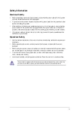
• Before installing or removing signal cables, ensure that the power cables for the system
unit and all attached devices are unplugged.
• To prevent electrical shock hazard, disconnect the power cable from the electrical outlet
before relocating the system.
• When adding or removing any additional devices to or from the system, ensure that the
power cables for the devices are unplugged before the signal cables are connected. If
possible, disconnect all power cables from the existing system before you add a device.
• If the power supply is broken, do not try to fix it by yourself. Contact a qualified service
technician or your dealer.
Operation Safety
• Any mechanical operation on this server must be conducted by certified or experienced
engineers.
• Before operating the server, carefully read all the manuals included with the server
package.
• Before using the server, ensure all cables are correctly connected and the power cables
are not damaged. If any damage is detected, contact your dealer as soon as possible.
• To avoid short circuits, keep paper clips, screws, and staples away from connectors,
slots, sockets and circuitry.
• Avoid dust, humidity, and temperature extremes. Place the server on a stable surface.
This product is equipped with a three-wire power cable and plug for the user’s safety. Use
the power cable with a properly grounded electrical outlet to avoid electrical shock.
Summary of Contents for 90SV038A-M34CE0
Page 1: ...1U Rackmount Server RS300 E9 PS4 RS300 E9 RS4 User Guide ...
Page 22: ...Chapter 1 Product Introduction 1 10 ...
Page 48: ...Chapter 2 Hardware Information 2 26 ...
Page 54: ...Chapter 4 Motherboard Information 4 2 4 1 Motherboard layout ...
Page 97: ...5 19 ASUS RS300 E9 Series Intel Server Platform Services Intel TXT Information ...
Page 146: ...6 18 Chapter 6 RAID Configuration ...
Page 157: ...ASUS RS300 E9 Series 7 11 8 Press Restart Now to complete the setup process ...
Page 163: ...Appendix A Appendix ...
Page 164: ...A 2 Appendix P10S C 4L SYS block diagram ...
Page 168: ...A 6 Appendix ...


