Chapter 1: Product Introduction
1-6
1.4
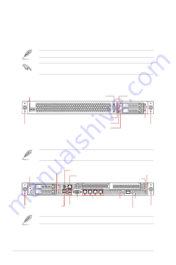
Front panel features
The barebone server displays a simple yet stylish front panel with easily accessible features.
The power and reset buttons, LED indicators, and USB ports for each Node are located on
the front panel.
Refer to the
1.7.1 Front panel LEDs
section for the LED descriptions.
Turn off the system power and detach the power supply before removing or replacing any
system component.
RS200-E9-PS2
1
2
3
4
Q-Code
1
2
3
4
RS200-E9-PS2-F
1
2
3
4
1
2
3
4
Q-Code
Hot-swap 2.5-inch
SSD Bays
refer to 1.7 LED information
Location button
Power button
COM port (optional)
Asset tag
Reset button
Rack screw
Rack screw
Rack screw
Rack screw
Location LED
Power button
2 x USB 3.0 ports
2 x USB 2.0 ports
Power connector
Hot-swap 2.5-
inch SSD Bays
Message
LED
LAN port 1-4
PS/2 keyboard/mouse combo port
DM management LAN port*
VGA port
Q-Code
display panel
*
This port is for ASUS ASMB8-iKVM controller and for technicians only.
The ports for the USB, VGA, and Gigabit LANs do not appear on the front panel if the
motherboard is not present.
Asset tag
Summary of Contents for 90SV045A-M05CE0
Page 1: ...1U Rackmount Server User Guide RS200 E9 Series RS200 E9 PS2 RS200 E9 PS2 F ...
Page 12: ...xii ...
Page 26: ...Chapter 1 Product Introduction 1 14 ...
Page 58: ...Chapter 4 Motherboard Information 4 2 4 1 Motherboard layout ...
Page 100: ...5 18 Chapter 5 BIOS Setup Intel Server Platform Services Intel TXT Information ...
Page 130: ...5 48 Chapter 5 BIOS Setup ...
Page 148: ...6 18 Chapter 6 RAID configuration ...
Page 158: ...7 10 Chapter 7 Driver Installation 8 Press Restart Now to complete the setup process ...
Page 163: ...Appendix Appendix ...
Page 164: ...A 2 Appendix P10S C 4L SYS block diagram ...
Page 168: ...A 6 Appendix ...


