background image

Motherboard

A7V600 SE

User Guide

Summary of Contents for A7V600 SE

Page 1: ...Motherboard A7V600 SE User Guide ...

Page 2: ... PARTICULAR PURPOSE IN NO EVENT SHALL ASUS ITS DIRECTORS OFFICERS EMPLOYEES OR AGENTS BE LIABLE FOR ANY INDIRECT SPECIAL INCIDENTAL OR CONSEQUENTIAL DAMAGES INCLUDING DAMAGES FOR LOSS OF PROFITS LOSS OF BUSINESS LOSS OF USE OR DATA INTERRUPTION OF BUSINESS AND THE LIKE EVEN IF ASUS HAS BEEN ADVISED OF THE POSSIBILITY OF SUCH DAMAGES ARISING FROM ANY DEFECT OR ERROR IN THIS MANUAL OR PRODUCT SPECIF...

Page 3: ... 6 Before you proceed 1 10 1 7 Motherboard installation 1 11 1 7 1 Placement direction 1 11 1 7 2 Screw holes 1 11 1 8 Central Processing Unit CPU 1 12 Installing the CPU 1 12 1 9 System memory 1 13 DDR400 Qualified Vendor List 1 13 1 10 Expansion slots 1 15 1 10 1 Configuring an expansion card 1 15 1 10 2 Standard interrupt assignments 1 15 IRQ assignments for this motherboard 1 16 1 10 3 AGP slo...

Page 4: ...Menu 2 23 2 5 1 Power Up Control 2 25 2 5 2 Hardware Monitor 2 26 2 6 Boot Menu 2 27 2 7 Exit Menu 2 29 Chapter 3 Software support 3 1 Install an operating system 3 2 3 2 Support CD information 3 2 3 2 1 Running the support CD 3 2 3 2 2 Drivers menu 3 3 3 2 3 Utilities menu 3 3 3 2 4 ASUS Contact Information 3 4 3 3 ASUS Instant Music Lite 3 5 3 4 RAID 0 RAID 1 RAID 0 1 Configurations 3 7 3 4 1 In...

Page 5: ...use harmful interference to radio or television reception which can be determined by turning the equipment off and on the user is encouraged to try to correct the interference by one or more of the following measures Reorient or relocate the receiving antenna Increase the separation between the equipment and receiver Connect the equipment to an outlet on a circuit different from that to which the ...

Page 6: ...your area If you are not sure about the voltage of the electrical outlet you are using contact your local power company If the power supply is broken do not try to fix it by yourself Contact a qualified service technician or your retailer Operation safety Before installing the motherboard and adding devices on it carefully read all the manuals that came with the package Before using the product ma...

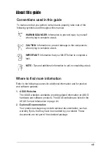
Page 7: ...ntation such as warranty flyers that may have been added by your dealer These documents are not part of the standard package About this guide Conventions used in this guide To make sure that you perform certain tasks properly take note of the following symbols used throughout this manual WARNING DANGER Information to prevent injury to yourself when trying to complete a task CAUTION Information to ...

Page 8: ...SA Fax 1 510 608 4555 E mail tmd1 asus com Web site usa asus com Technical Support Telephone General 1 502 995 0883 Notebook 1 510 739 3777 Support fax 1 502 933 8713 Support e mail tsd asus com ASUS COMPUTER GmbH Germany and Austria Address Harkort Str 25 D 40880 Ratingen Germany Telephone 49 2102 9599 0 Fax 49 2102 9599 11 Online contact www asuscom de sales Technical Support Telephone 49 2102 9...

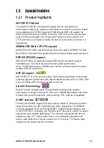
Page 9: ...t qualified DDR400 module list 1 x AGP 8X 6 x PCI 1 x ASUS Proprietary WiFi wireless LAN connector 2 x UltraDMA 133 100 66 2 x Serial ATA with RAID 0 RAID 1 and JBOD support ADI AD1980 SoundMAX 6 channel CODEC S PDIF out interface Marvell 88E8001 Gigabit LAN controller Virtual Cable Tester VCT Technology support ASUS EZ Flash Power Loss Restart ASUS C O P CPU Overheating Protection ASUS CrashFree ...

Page 10: ...X Modem audio in S PDIF out connector Front panel audio connector 2 x USB 2 0 connector supports additional 4 USB 2 0 ports 2 x Serial ATA port COM2 connector 2Mb Flash ROM ASUS Jumperfree Award BIOS PnP DMI2 0 WfM2 0 SM BIOS2 3 ASUS EZ Flash ASUS CrashFree BIOS 2 ASUS C P R PCI 2 2 USB 2 0 WfM 2 0 DMI 2 0 WOR WOL chassis intrusion ATX form factor 12 in x 9 6 in 30 5 cm x 24 5 cm Device drivers AS...

Page 11: ...E Motherboard This chapter gives information about the ASUS A7V600 SE motherboard that came with the system This chapter includes the motherboard layout jumper settings and connector locations Motherboard Info Chapter 1 ...

Page 12: ...P R CrashFree BIOS2 Q Fan and more are included to ensure the best user experience and value in a motherboard Before you start installing the motherboard and hardware devices on it check the items in your package with the list below 1 2 Package contents Check your ASUS A7V600 SE package for the following items ASUS A7V600 SE motherboard ATX form factor 12 in x 9 6 in 30 5 cm x 24 5 cm ASUS A7V600 ...

Page 13: ... website for the latest qualified DDR400 module list AGP 8X support AGP 8X AGP 3 0 is the next generation VGA interface specification that enables enhanced graphics performance with high bandwidth speeds up to 2 12 GB s With a bus of 533Mhz AGP 8X is twice as fast as AGP 4X Serial ATA technology Serial ATA is the next generation ATA specification that provides scalable performance for today and to...

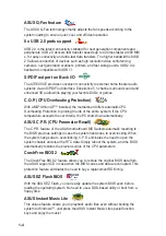
Page 14: ...ing Protection to prolong the life of the entire system If the CPU temperature exceeds the set criteria the PC shuts down automatically ASUS C P R CPU Parameter Recall The C P R feature of the ASUS motherboard BIOS allows automatic resetting to the BIOS previous settings in case the system hands due to overclocking When the system hangs due to overclocking C P R eliminates the need to open the sys...

Page 15: ... monitored by the system to prevent overheating and damage The system fan rotations per minute RPM is monitored for timely failure detection The system voltage levels are monitored to ensure stable supply of current for critical components Chassis intrusion detection The motherboard supports chassis intrusion monitoring A chassis intrusion event is retained in CMOS for more protection ASUS update ...

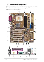
Page 16: ...you install the motherboard learn about its major components and available features to facilitate the installation and future upgrades Refer to the succeeding pages for the component descriptions 3 2 7 1 13 9 16 11 5 4 6 10 14 15 17 18 12 8 19 29 22 23 24 25 20 21 27 28 26 ...

Page 17: ...ommodates the provided ribbon cable for the floppy disk drive One side of the connector is slotted to prevent incorrect insertion of the floppy disk cable AGP slot This Accelerated Graphics Port AGP slot supports 1 5V AGP8X mode graphics cards for 3D graphical applications Serial ATA connectors These two 7 pin connectors accommodate the thin cables for Serial ATA devices South bridge controller Th...

Page 18: ...s connection to a Local Area Network LAN through a network hub Line In jack This Line In light blue jack connects a tape player or other audio sources In 6 channel mode the function of this jack becomes Rear Speaker Out Line Out jack This Line Out lime jack connects a headphone or a speaker In 6 channel mode the function of this jack becomes Front Speaker Out Microphone This Mic pink jack connects...

Page 19: ...SB4 B USB3 Top RJ 45 GAME CHASSIS FLOPPY PRI_IDE SEC_IDE SPDIF_OUT2 ATX Power Connector DDR DIMM1 64 72 bit 184 pin module PWR_FAN KBPWR CHA_FAN SB_PWR VIA VT8237 South Bridge Marvell Gigabit LAN COM2 USB56 MODEM CR2032 3V Lithium Cell CMOS Power USBPW34 WIFI CLRTC USBPW56 USB1 USB2 PARALLEL PORT SPDIF_O COM1 PCI2 PCI3 PCI4 PCI5 PCI6 DDR DIMM2 64 72 bit 184 pin module DDR DIMM3 64 72 bit 184 pin m...

Page 20: ...ll any component place it on a grounded antistatic pad or in the bag that came with the component 5 Before you install or remove any component ensure that the ATX power supply is switched off or the power cord is detached from the power supply Failure to do so may cause severe damage to the motherboard peripherals and or components When lit the green LED SB_PWR indicates that the system is ON in s...

Page 21: ...at you place it into the chassis in the correct orientation The edge with external ports goes to the rear part of the chassis as indicated in the image below 1 7 2 Screw holes Place nine 9 screws into the holes indicated by circles to secure the motherboard to the chassis Make sure to unplug the power cord before installing or removing the motherboard Failure to do so may cause you physical injury...

Page 22: ... With the added weight of the CPU fan and heatsink locking brace no extra force is required to keep the CPU in place Installing the CPU Follow these steps to install a CPU 1 Locate the Socket 462 and open it by pulling the lever gently sideways away from the socket Then lift the lever upwards The socket lever must be fully opened 90 to 100 degrees 2 Insert the CPU with the correct orientation The ...

Page 23: ...lowing table lists the PC3200 DDR400 memory modules that have been tested and qualified for use with this motherboard Make sure to use only the tested and qualified DDR400 DIMMs listed below Visit the ASUS website www asus com for the latest DDR Qualified Vendors List PC3200 maximum to 2 banks only Continued on the next page SS Size Vendor Part Number Brand DS Chip Number A B 256MB TwinMos M2G9I08...

Page 24: ...2MB Hynix HYMD264646B8J D43 AA Hynix DS HY5DU56822BT D43 512MB PSC AL6D8A53T1 5B PSC DS A2S56D30ATP 256MB TwinMos M2S9I08AFAPS9F0811A T PSC SS A2S56D30ATP 512MB KINGMAX MPXB62D 68KX3 Kingmax DS KDL684T4AA 50 512MB Micron MT16VDDT6464AG 40BC4 Micron DS MT46V32M8TG 5BC 256MB ATP AG32L64T8SQC4S Samsung SS K4H560838D TCC4 128MB NANYA NT128D64SH4B1G 5T NANYA SS NT5DS16M16BT 5T 256MB NANYA NT256D64S88B1...

Page 25: ...ible Mouse Port 13 8 Numeric Data Processor 14 9 Primary IDE Channel 15 10 Secondary IDE Channel These IRQs are usually available for ISA or PCI devices 1 10 Expansion slots The A7V600 SE motherboard has six 6 expansion PCI slots and one 1 AGP 8X slot The following sub sections describe the slots and the expansion cards that they support 1 10 1 Configuring an expansion card After physically instal...

Page 26: ...t they fit the AGP slot on your motherboard A7V600 SE A7V600 SE Accelerated Graphics Port AGP Keyed for 1 5v IRQ assignments for this motherboard A B C D E F G H PCI slot 1 shared PCI slot 2 shared PCI slot 3 shared PCI slot 4 shared PCI slot 5 shared PCI slot 6 shared AGP slot shared USB 1 1 UHCI 1 shared USB 1 1 UHCI 2 shared USB 1 1 UHCI 3 shared USB 1 1 UHCI 4 shared USB 2 0 EHCI shared USB De...

Page 27: ...ule Visit the ASUS website www asus com for product updates The Wi Fi slot conforms to the Institute of Electrical and Electronics Engineers IEEE 802 11b g standard for wireless devices operating in the 2 4 GHz frequency band ASUS WiFi b Setup The PCI 6 slot and the Wi Fi slot can not be used at the same time The ASUS WiFi b module is purchased separately ...

Page 28: ...s feature requires a power supply that can provide at least 2A on the 5VSB lead when these jumpers are set to 5VSB Otherwise the system does not power up 2 The total current consumed must NOT exceed the power supply capability 5VSB whether under normal or in sleep mode A7V600 SE A7V600 SE USB Device Wake Up USBPW12 USBPW34 3 2 2 1 5V Default 5VSB USBPW78 USBPW56 3 2 2 1 5V Default 5VSB 2 Keyboard ...

Page 29: ... 3 seconds 4 Re install the battery 5 Plug the power cord and turn ON the computer 6 Hold down the Del key during the boot process and enter BIOS setup to re enter data A7V600 SE A7V600 SE Clear RTC RAM CLRTC Normal Clear CMOS Default 1 2 2 3 4 VCORE over voltage 3 pin OVER_VOLT1 When enabled this jumper allows CPU VCORE ranges of 1 7V to 2 05V When this jumper is disabled VCORE setting has a rang...

Page 30: ...ordingly Refer to the hard disk documentation for the jumper settings BIOS supports specific device bootup If you have more than two UltraDMA 133 100 66 devices purchase another UltraDMA 133 100 66 cable You may configure two hard disks to be both master devices with two ribbon cables one for the primary IDE connector and another for the secondary IDE connector 1 Pin 20 on each IDE connector is re...

Page 31: ...nd Ground are shorted with a jumper cap If you wish to use the chassis intrusion detection feature remove the jumper cap from the pins A7V600 SE A7V600 SE Chassis Alarm Lead CHASSIS 5VSB_MB Chassis Signal GND Default 2 Floppy disk drive connector 34 1 pin FLOPPY This connector supports the provided floppy drive ribbon cable After connecting one end to the motherboard connect the other end to the f...

Page 32: ...tors CPU_FAN CHA_FAN GND Rotation 12V PWR_FAN GND Rotation 12V GND Rotation 12V 5 ATX power connectors 20 pin ATXPWR1 These connectors connect to an ATX 12V power supply The plugs from the power supply are designed to fit these connectors in only one orientation Find the proper orientation and push down firmly until the connectors completely fit Make sure that your ATX 12V power supply can provide...

Page 33: ...rs and printers A7V600 SE A7V600 SE USB 2 0 Header USB56 USB 5V USB_P6 USB_P6 GND NC USB 5V USB_P5 USB_P5 GND 1 USB78 USB 5V USB_P8 USB_P8 GND NC USB 5V USB_P7 USB_P7 GND 1 7 Internal audio connectors 4 pin CD AUX MODEM These connectors allow you to receive stereo audio input from sound sources such as a CD ROM TV tuner or MPEG card The MODEM connector allows the onboard audio to interface with a ...

Page 34: ...dio files A7V600 SE A7V600 SE Game Connector GAME 5V 5V J2B1 J2CX MIDI_OUT J2CY J2B2 MIDI_IN J1B1 J1CX GND GND J1CY J1B2 5V 9 Serial port connector 10 1 pin COM2 This green connector accomodate a second serial port using an optional serial port bracket Connect the bracket cable to this connector then install the bracket with green port into a slot opening at the back of the system chassis The COM2...

Page 35: ...t panel audio cable A7V600 SE A7V600 SE Front Panel Audio Connector FP_AUDIO BLINE_OUT_L MIC2 Line out_R Line out_L BLINE_OUT_R NC MICPWR 5VA AGND 10 Digital audio connector 6 1 pin SPDIF_OUT2 This connector is for the S PDIF audio module that allows digital instead of analog sound output Connect one end of the audio cable to the S PDIF Out connector on the motherboard and the other end to the S P...

Page 36: ...nks when the system is in sleep mode System Warning Speaker Lead 4 pin SPKR This 4 pin connector connects to the case mounted speaker and allows you to hear system beeps and warnings Reset Switch Lead 2 pin RESET This 2 pin connector connects to the case mounted reset switch for rebooting the system without turning off the system power 12 Serial ATA connector 7 pin SATA1 SATA2 These connectors acc...

Page 37: ...e system OFF System Management Interrupt Lead 2 pin SMI This 2 pin connector allows you to manually place the system into a suspend mode or green mode where system activity is instantly decreased to save power and to expand the life of certain system components Attach the case mounted suspend switch to this 2 pin connector Hard Disk Activity Lead 2 pin IDE_LED This connector supplies power to the ...

Page 38: ...1 28 Chapter 1 Motherboard Information ...

Page 39: ...ASUS A7V600 SE Motherboard 2 1 This chapter tells how to change the system settings through the BIOS setup menus Detailed descriptions of the BIOS parameters are also provided BIOS Information Chapter 2 ...

Page 40: ...ontains the new BIOS file into the floppy drive You will receive the error message WARNING Device not ready if you proceed to step 5 without the disk in the drive ASUS EZ Flash V1 00 Copyright C 2002 ASUSTeK COMPUTER INC Onboard BIOS Information BIOS Version ASUS A7V600 SE BIOS Revision 1001 Beta 003 BIOS Model A7V600 SE BIOS Built Date 06 03 03 Please Enter File Name for NEW BIOS _ Note EZ Flash ...

Page 41: ...exits the EZ Flash screen and reboots the system without updating the BIOS The following prompts appear if you typed Y 7 Press Y for both items to completely update the main BIOS area and the boot block area BIOS Information in File BIOS Version A7V600 SE Boot Block WARNING Continue to update the BIOS Y N _ 8 When the update process is done the message Press a key to reboot appears Press any key t...

Page 42: ...otable system disk DO NOT copy AUTOEXEC BAT and CONFIG SYS to the disk 2 Type COPY D AFLASH AFLASH EXE A assuming D is your CD ROM drive to copy AFLASH EXE to the boot disk you created 4 In DOS mode type A AFLASH Enter to run AFLASH 3 Reboot the computer from the floppy disk AFLASH works only in DOS mode It does not work with certain memory drivers that may be loaded when you boot from the hard dr...

Page 43: ...S Including Boot Block and ESCD screen appears 5 Type the filename of your new BIOS and the path for example A XXX XX XXX then press Enter To cancel this operation press Enter Updating the BIOS 5 Select 1 Save Current BIOS to File from the Main menu and press Enter The Save Current BIOS To File screen appears 6 Type a filename and the path for example A XXX XX XXX then press Enter Update the BIOS ...

Page 44: ...y When the programming is done the message Flashed Successfully appears 8 Follow the onscreen instructions to continue DO NOT turn off the system while updating the BIOS This may cause boot problems Just repeat the process and if the problem persists load the original BIOS file you saved to the boot disk If the Flash Memory Writer utility is not able to successfully update a complete BIOS file cal...

Page 45: ...test BIOS file for this motherboard If all the necessary files are found in the floppy disk the BIOS update process continues Bad BIOS checksum Starting BIOS recovery Checking for floppy Floppy found Reading file A7V6SE01 AWD Completed Start flashing 4 When the BIOS update process is complete reboot the system 1 Prepare the support CD that came with the motherboard or a floppy disk that contains t...

Page 46: ...OS update process is complete reboot the system Bad BIOS checksum Starting BIOS recovery Checking for floppy Floppy not found Checking for CD ROM CD ROM found Reading file A7V6SE01 AWD Completed Start flashing If there is no floppy disk found in the drive the system automatically checks the CD ROM DO NOT shutdown or reset the system while updating the BIOS Doing so may cause system boot failure Th...

Page 47: ...the Setup utility otherwise POST continues with its test routines The Setup program is designed to make it as easy to use as possible It is a menu driven program which means you can scroll through the various sub menus and make your selections among the predetermined choices Because the BIOS software is constantly being updated the following BIOS setup screens and descriptions are for reference pu...

Page 48: ...r the highlighted field Home or PgUp Moves the cursor to the first field End or PgDn Moves the cursor to the last field F5 Resets the current screen to its Setup Defaults F10 Saves changes and exits Setup General help In addition to the Item Specific Help window the BIOS setup program also provides a General Help screen You may launch this screen from any menu by simply pressing F1 or the Alt H co...

Page 49: ...nd sub menus If you accidentally make unwanted changes to any of the fields use the set default hot key F5 to load the Setup default values While moving around through the Setup program note that explanations appear in the Item Specific Help window located to the right of each menu This window displays the help text for the currently highlighted field System Time XX XX XX Sets the system to the ti...

Page 50: ...ht this field and press Enter The same dialog box as above appears Press Enter The password is set to Disabled Make a copy of the original BIOS on a bootable floppy disk before setting passwords You will need to upload the BIOS file in case you erase the CMOS RAM in the future A note about passwords The BIOS Setup program allows you to specify passwords in the Main menu The passwords control acces...

Page 51: ...pe HDD Manually enter the number of cylinders heads and sectors per track for the drive Refer to the drive documentation or label for this information Before attempting to configure a hard disk drive make sure you have the correct configuration information supplied by the drive manufacturer Halt On All Errors This field specifies the types of errors that will cause the system to halt Configuration...

Page 52: ...ge capacity Configuration options LBA LARGE Normal Match Partition Table Manual Cylinders This field configures the number of cylinders Refer to the drive documentation to determine the correct value To make changes to this field set the Type field to User Type HDD and the Translation Method field to Manual Head This field configures the number of read write heads Refer to the drive documentation ...

Page 53: ...r Type HDD Configuration options 0 1 2 3 4 5 6 Disabled Multi Sector Transfers Maximum This option automatically sets the number of sectors per block to the highest number that the drive supports Note that when this field is automatically configured the set value may not always be the fastest value for the drive You may also manually configure this field Refer to the documentation that came with t...

Page 54: ...o send to the system bus and PCI bus The bus frequency external frequency multiplied by the bus multiple equals the CPU speed Memory Frequency MHz This field determines the memory clock frequency Configuration options Auto 266 333 400 CPU VCore Setting Auto The Manual setting allows you to manually select the core voltage supplied to the CPU see next item It is recommended that you keep the defaul...

Page 55: ... to detect a PS 2 mouse at startup If a mouse is detected the BIOS assigns IRQ12 to the PS 2 mouse Otherwise IRQ12 can be used for expansion cards When you set this field to Enabled BIOS reserves IRQ12 whether or not a PS 2 mouse is detected at startup Configuration options Enabled Auto USB Legacy Support Auto This motherboard supports Universal Serial Bus USB devices The default of Auto allows th...

Page 56: ...iguration to User Defined 2 4 1 Chip Configuration Instant Music CD ROM Allows you to select the CD ROM drive that you wish to use for the Instant Music CD playback Configuration options depends on the optical drives installed on your system The above item appears only if you enabled the Instant Music item When Instant Music is enabled the PS 2 keyboard power up feature is automatically disabled S...

Page 57: ...cs card AGP Capability 8X Mode This motherboard supports the AGP 8X interface that enables enhanced graphics performance with high bandwidth speeds up to 2 12GB s AGP8X is backward compatible When set to 1X Mode the AGP interface only provides a peak data throughput of 266MB s even if you are using an AGP 8X card Configuration options Auto 1X Mode 2X Mode 4X Mode 8X Mode AGP Drive Strength Auto Co...

Page 58: ...s Control R W When set to Read Only this item protects files from being copied to floppy disks by allowing reads from but not writes to the floppy disk drive The default setting R W allows both reads and writes Configuration options R W Read Only Onboard Serial Port 1 3F8H IRQ4 Onboard Serial Port 2 2F8H IRQ3 These fields allow you to set the addresses for the onboard serial connectors Serial Port...

Page 59: ... select ECP or ECP EPP in Parallel Port Mode above Configuration options 1 3 Onboard Game Port 200H 207H These fields allow you to set the addresses for the onboard game connectors Game ports must have different addresses Configuration options 200H 207H 208H 20FH Disabled Onboard MIDI I O Disabled These fields allow you to set the addresses for the onboard MIDI connectors MIDI ports must have diff...

Page 60: ...9 10 11 12 14 15 PCI VGA Palette Snoop Disabled Some non standard VGA cards like graphics accelerators or MPEG video cards may not show colors properly Setting this field to Enabled corrects this problem If you are using standard VGA cards leave this field to the default setting Disabled Configuration options Disabled Enabled PCI Latency Timer 32 Leave this field to the default setting 32 for best...

Page 61: ...res a unique IRQ and you are NOT using ICU Configuration options No ICU Yes Power Management User Defined This field allows you to activate or deactivate the automatic power saving features When set to Disabled the power management features do not function regardless of the other settings on this menu The User Defined option allows you to set the period of inactivity before the system enters suspe...

Page 62: ...witch can be used as a normal system power off button when pressed for less than 4 seconds Suspend allows the button to have a dual function where pressing less than 4 seconds puts the system in sleep mode Regardless of the setting holding the ATX switch for more than 4 seconds powers off the system Configuration options Soft off Suspend You should install the Advanced Power Management APM utility...

Page 63: ...tem This feature requires an ATX power supply that provides at least 1A on the 5VSB lead Configuration options Disabled Space Bar Ctrl Esc Power Key Wake Power On By PS 2 Mouse Disabled When set to Double Click this parameter allows you to use the PS 2 mouse to turn on the system This feature requires an ATX power supply that provides at least 1A on the 5VSB lead Configuration options Disabled Dou...

Page 64: ...he onboard voltage regulators Q Fan Control Disabled This item allows you to enable or disable the ASUS Q Fan feature that smartly adjusts the fan speeds for more efficient system operation When this field is set to Enabled the Fan Speed Ratio and Speed Up Down Response Time items appear to allow selection of the appropriate fan speeds and the corresponding response time Configuration options Disa...

Page 65: ...be prompted to Press F1 to continue or DEL to enter SETUP 2 6 Boot Menu Boot Sequence The Boot menu allows you to select four types of boot devices using the up and down arrow keys By using the or Space key you can promote devices and by using the key you can demote devices Promotion or demotion of devices alters the priority which the system uses to boot device on system power up Configuration fi...

Page 66: ...OST Configuration options No Yes Boot Virus Detection Enabled This field allows you to set boot virus detection ensuring a virus free boot sector The system halts and displays a warning message when it detects a virus If this occurs you can either allow the operation to continue or use a virus free bootable floppy disk to restart and investigate your system Configuration options Disabled Enabled Q...

Page 67: ...hanges the program prompts you with a message asking if you want to save your changes before exiting Pressing Enter saves the changes while exiting Pressing Esc does not immediately exit this menu Select one of the options from this menu or F10 from the legend bar to exit Exit Discarding Changes Select this option only if you do not want to save the changes that you made to the Setup program If yo...

Page 68: ...g this option a confirmation appears Select Yes to discard any changes and load the previously saved values Save Changes This option saves your selections without exiting the Setup program You can then return to other menus and make further changes After you select this option a confirmation window appears Select Yes to save any changes to the non volatile RAM ...

Page 69: ...3 1 ASUS A7V600 SE Motherboard This chapter helps you power up your system and install drivers and utilities that came with the support CD Starting Up Chapter 3 ...

Page 70: ... CD that came with the motherboard contains useful software and several utility drivers that enhance the motherboard features 3 2 1 Running the support CD To begin using the support CD simply insert the CD into your CD ROM drive The CD automatically displays the Drivers menu if Autorun is enabled in your computer Click an icon to display more information Click an item to install The contents of th...

Page 71: ...vers VIA Registry INF driver VIAAGP VxD driver VIAATAPI vendor support driver VIA PCI IRQ Miniport driver Marvell Gigabit LAN Driver This item installs the Marvell Gigabit LAN drivers and utilities for Gigabit LAN solution that provides up to 1000Mbps data transfer rates VIA RAID Controller Driver This item installs the VIA RAID controller drivers for RAID configurations SoundMAX Audio Driver This...

Page 72: ...in 2002 V9 02 anti virus software ADOBE Acrobat Reader V5 0 This installs software for viewing files in Portable Document Format PDF ASUS Screen Saver This item installs the ASUS screen saver 3 2 4 ASUS Contact Information Clicking the ASUS Contact Information tab displays as stated You may also find this information on page viii of this user guide ...

Page 73: ... CD ROM drive that you wish to use for this feature See section 2 4 Advanced Menu in the user guide 1 The Scroll Lock LED is fixed to ON after enabling Instant Music 2 The Caps Lock LED is turns ON when you pause the CD playback 3 When set to Instant Music Lite mode the system wake up features LAN keyboard mouse USB are deactivated In this case power up the system using the power switch 4 If the s...

Page 74: ...put You may also connect a headphone to the headphone jack on the CD ROM drive front panel 4 Press Esc to turn ON Instant Music Lite 5 Place an audio CD on the drive 6 Press F1 or the Space Bar to play the first track on the CD 7 Refer to the Instant Music function key definitions on the previous page to select other tracks or control the volume 8 Press F2 or Enter once to stop playing the CD Pres...

Page 75: ...alled data mirroring copies and maintains an identical image of data from one drive to a second drive If one drive fails the disk array management software directs all applications to the surviving drive as it contains a complete copy of the data in the other drive This RAID configuration provides data protection and increases fault tolerance to the entire system JBOD for just a bunch of disks or ...

Page 76: ...to the drive bays 2 Connect one end of the Serial ATA cable to the motherboard s primary Serial ATA connector SATA1 3 Connect the other end of Serial ATA cable to the master Serial ATA hard disk 4 Connect one end of the second Serial ATA cable to the motherboard s secondary Serial ATA connector SATA2 5 Connect the other end of Serial ATA cable to the secondary Serial ATA hard disk 6 Connect the Se...

Page 77: ...e a RAID array with the hard disk attached to VIA IDE controller F1 View Array Disk Status Move to next item Enter Confirme the selection ESC Exit On the upper right side of the screen is the message and legend box The keys on the legend box allows you to navigate through the setup menu options The message describes the function of each menu item The following lists the keys found in the legend bo...

Page 78: ... ESC Exit RAID 0 for performance 1 Select the second option item Array Mode then press the Enter key The RAID system setting pop up menu appears 2 Select RAID 0 for performance from the menu and press Enter From this point you may choose to auto configure the RAID array by selecting Auto Setup for Performance or manually configure the RAID array for stripped sets If you want to manually configure ...

Page 79: ...on the selected disks will be destroyed Continue Press Y N 4K 8K 16K 32K 64K RAID 0 for performance RAID 1 for data protection RAID 0 1 RAID SPAN for capacity RAID 1 for data protection Create only Create and duplicate Create only 3 Select task and press Enter The screen returns to Create Array menu items From this point you may choose to auto configure the RAID array by selecting Auto Setup for D...

Page 80: ...em setting pop up menu appears RAID 0 for performance RAID 1 for data protection RAID 0 1 RAID SPAN for capacity RAID SPAN for capacity 2 Select RAID SPAN for capacity from the menu and press Enter From this point you may choose to auto configure the RAID array by selecting Auto Setup for Capacity or manually configure the RAID array for spanned sets If you want to manually configure the RAID arra...

Page 81: ... of channel used for IDE RAID arrays 2 Press the Enter key to select a RAID array to delete The following confirmation message appears Press Y to confirm or N to return to the configuration options The selected array will be destroyed Are you sure Continue Press Y N 4 Select Start Create Process and press Enter to setup hard disk for RAID system The following confirmation message appears Press Y t...

Page 82: ...m of the screen This option is useful for identifying same model disks Channel Drive Name Array Name Mode Size GB Status Serial_Ch0 Master XXXXXXXXXX xxxxx xxx xx Hdd Serial_Ch1 Master XXXXXXXXXX xxxxx xxx xx Hdd VIA Tech RAID BIOS Ver 1 xx Create Array Delete Array Create Delete Spare Select Boot Array Serial Number View Create a RAID array with the hard disk attached to VIA IDE controller F1 Vie...

Page 83: ...reduces networking and support costs complementing a highly manageable and controlled network system Also this tool can be incorporated in the network systems software making it ideal for field support as well as development diagnostics Using the Virtual Cable Tester To use the the Marvell Virtual Cable Tester on your computer 1 Click the Start button Select All Programs Marvell Virtual Cable Test...

Page 84: ...3 16 Chapter 3 Starting Up ...

Reviews: