Chapter 2 – Hardware Information
12
Io
T G
at
eway
S
yste
m
AIO
T-
Q
M
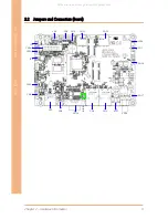
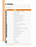
2.4 List of Connectors
Please refer to the table below for all of the board’s connectors that you can configure
for your application
Label
Function
CN1
JTAG Programming Port Box Header
CN2
Battery Box Header
CN3
ADC Box Header
CN4
10/100 RJ-45 Connector (LAN1)
CN5
10/100 RJ-45 Connector (LAN2)
CN6
Mini USB Host Port Connector
CN7
Hub Dual USB Connector (USB1,2)
CN8
Hub Dual USB (USB3,4)
CN9
Digital I/O
CN10
ZigBee / Energy SPI Module Box Header
CN11
I2C Box Header
CN12
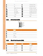
Micro SD Card Connector
CN14
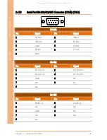
Serial Port RS-232/422/485 Connector (COM1)
CN15
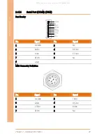
Serial Port (COM2)
CN16
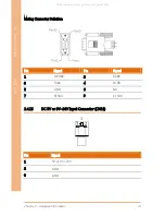
DC 5V or 9V~24V Input Connector
CN17
DC 5V or 9V~24V Input
CN18
Power LED Box Header
CN21
Mini PCI-E Slot
CN35
Micro SIM Socket
J1
Reset
J2
SPI Flash
LED1
Micro SD LED
LED2
VCC Power OK LED
All manuals and user guides at all-guides.com


