Preface
XI
EPIC
Bo
ar
d
EPIC
-C
FS
7
Table of Contents
Front Panel PIN Header (JP1) ..................................................................... 8
AT/ATX mode Selection (JP2) .................................................................... 9
Clear CMOS Jumper (JP3) .......................................................................... 9
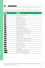
2 Pin DC IN Connector (CN5) .................................................................. 13
DIO Power Connector (CN6) .................................................................... 13
PCIe [x4] FPC Connector (CN9) ...............................................................14
CPU FAN Connector (CN10) ..................................................................... 15
POE LAN (RJ-45) Connector (CN11) ....................................................... 15
RS232/422/485 connector COM1, COM2 (CN12/13) .......................... 16
HDMI Connector (CN14/15) ...................................................................... 18
USB 3.2 Gen 2 Connector (CN16) ........................................................... 19
USB 3.2 Gen 2 Connector (CN17) ........................................................... 20
USB 2.0 Connector (CN19) ........................................................................ 21
Mini-Card Connector (CN20) ................................................................... 21
DDR4 SO-DIMM Slot (DIMM1 & DIMM2)............................................. 22
Summary of Contents for AAEON EPIC-CFS7
Page 1: ...Last Updated April 27 2021 EPIC CFS7 EPIC Board User s Manual 1st Ed ...
Page 14: ...EPIC Board EPIC CFS7 Chapter 1 Chapter 1 Product Specifications ...
Page 17: ...4 EPIC Board EPIC CFS7 Chapter 2 Chapter 2 Hardware Information ...
Page 18: ...Chapter 2 Hardware Information 5 EPIC Board EPIC CFS7 2 1 Dimensions ...
Page 19: ...Chapter 2 Hardware Information 6 EPIC Board EPIC CFS7 2 2 Jumpers and Connectors ...
Page 20: ...Chapter 2 Hardware Information 7 EPIC Board EPIC CFS7 ...
Page 36: ...Chapter 2 Hardware Information 23 EPIC Board EPIC CFS7 2 5 Block Diagram ...
Page 37: ...24 EPIC Board EPIC CFS7 Chapter 3 Chapter 3 BIOS Setup ...
Page 40: ...Chapter 3 BIOS Setup 27 EPIC Board EPIC CFS7 3 3 Setup Submenu Main ...
Page 41: ...Chapter 3 BIOS Setup 28 EPIC Board EPIC CFS7 3 4 Setup Submenu Advanced ...
Page 44: ...Chapter 3 BIOS Setup 31 EPIC Board EPIC CFS7 3 4 3 Hardware Monitor ...
Page 48: ...Chapter 3 BIOS Setup 35 EPIC Board EPIC CFS7 3 4 4 SIO Configuration ...
Page 53: ...Chapter 3 BIOS Setup 40 EPIC Board EPIC CFS7 3 5 Setup Submenu Chipset ...
Page 54: ...Chapter 3 BIOS Setup 41 EPIC Board EPIC CFS7 3 5 1 System Agent SA Configuration ...
Page 61: ...Chapter 3 BIOS Setup 48 EPIC Board EPIC CFS7 3 7 1 BBS Priorities ...
Page 62: ...Chapter 3 BIOS Setup 49 EPIC Board EPIC CFS7 3 8 Setup Submenu Save Exit ...
Page 63: ...50 EPIC Board EPIC CFS7 Chapter 4 Chapter 4 Driver Installation ...
Page 66: ...EPIC Board EPIC CFS7 Appendix A Appendix A I O Information ...
Page 67: ...Appendix A I O Information 54 EPIC Board EPIC CFS7 A 1 I O Address Map ...
Page 68: ...Appendix A I O Information 55 EPIC Board EPIC CFS7 ...
Page 69: ...Appendix A I O Information 56 EPIC Board EPIC CFS7 ...
Page 70: ...Appendix A I O Information 57 EPIC Board EPIC CFS7 A 2 Memory Address Map ...
Page 71: ...Appendix A I O Information 58 EPIC Board EPIC CFS7 A 3 IRQ Mapping Chart ...
Page 72: ...Appendix A I O Information 59 EPIC Board EPIC CFS7 ...
Page 73: ...Pico ITX Board EPIC CFS7 Appendix B Appendix B Watchdog Timer Programming ...

