Chapter 1
–
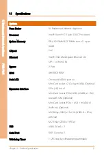
Product Specifications
3
1U
Rack
mou
nt
Net
work
Ap
pli
an
ce
FW
S-
75
41
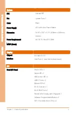
System
RTC
Internal RTC
Fan
System Fan x 1
Color
Black
Power Supply
ATX with Auto Power Button
Dimension
16.93” x 7.87” x
1.73” (430mm x 200mm x
44mm)
Power Requirement
AC/DC 1U Flex ATX 220W
MTBF (Hours)
-
Display
Chipset
Ice-Lake-D LCC
Interface
VGA Port x 1 (via VGA module board)
I/O
Front I/O Panel
Power LED x 1
Status LED x 1
HDD Active LED x 1
USB3.1 Ports x 2
Bypass LED x 2
RJ-45 Console x 1
RJ-45 IPMI Port x 1
Parallel LCM Display and 4 Keypad x 1
Software Programmable Button x 1
SFP+ Port 10Gb (from CPU) x 4
Summary of Contents for AAEON FWS-7541
Page 1: ...Last Updated July 6 2022 FWS 7541 1U Rackmount Network Appliance User s Manual 1st Ed ...
Page 14: ...1U Rackmount Network Appliance FWS 7541 Chapter 1 Chapter 1 Product Specifications ...
Page 18: ...1U Rackmount Network Appliance FWS 7541 Chapter 2 Chapter 2 Hardware Information ...
Page 20: ...Chapter 2 Hardware Information 7 1U Rackmount Network Appliance FWS 7541 ...
Page 21: ...Chapter 2 Hardware Information 8 1U Rackmount Network Appliance FWS 7541 Board Component Side ...
Page 22: ...Chapter 2 Hardware Information 9 1U Rackmount Network Appliance FWS 7541 Solder Side ...
Page 40: ...1U Rackmount Network Appliance FWS 7541 Chapter 3 Chapter 3 AMI BIOS Setup ...
Page 43: ...Chapter 3 AMI BIOS Setup 30 1U Rackmount Network Appliance FWS 7541 3 3 Setup Submenu Main ...
Page 47: ...Chapter 3 AMI BIOS Setup 34 1U Rackmount Network Appliance FWS 7541 3 4 2 Hardware Monitor ...
Page 50: ...Chapter 3 AMI BIOS Setup 37 1U Rackmount Network Appliance FWS 7541 3 4 4 SIO Configuration ...
Page 64: ...Chapter 3 AMI BIOS Setup 51 1U Rackmount Network Appliance FWS 7541 3 5 2 SATA Configuration ...
Page 70: ...Chapter 3 AMI BIOS Setup 57 1U Rackmount Network Appliance FWS 7541 3 5 8 Memory Topology ...
Page 71: ...Chapter 3 AMI BIOS Setup 58 1U Rackmount Network Appliance FWS 7541 3 5 9 IIO Configuration ...

