background image

7

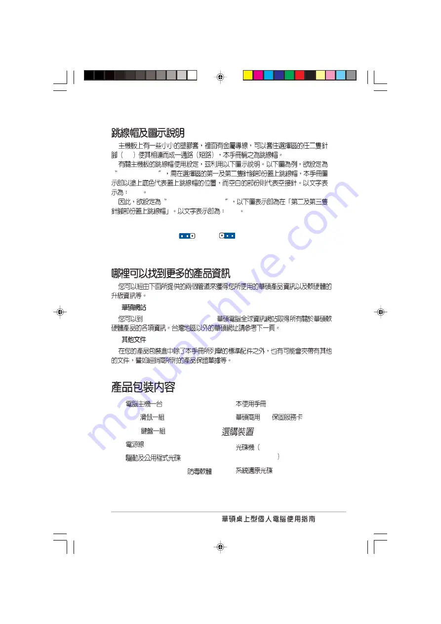
1.

 http://taiwan.asus.com.tw 

2.

Pin

Jumper Mode

[1-2]

JumperFree™ Mode

[2-3]

Jumper Free

(Default)

2 3

Jumper Mode

1 2

USB 

PS/2 

Norton AntiVirus 2004 

 PC 

CD-ROM/CD-RW/DVD-

ROM/DVD-RW

Summary of Contents for AS-D325

Page 1: ...AS D325 ...

Page 2: ...2 T1503 1 22 1 24 BIOS 2004 1 00 2004 2 ...

Page 3: ...8 9 10 1 1 1 1 1 2 1 2 1 2 1 2 1 1 2 1 2 2 1 3 1 2 3 1 4 1 2 4 1 5 1 3 1 6 1 4 1 8 1 5 P4S533 MX 1 14 1 6 1 13 1 7 P4S533 MX 1 14 1 7 1 1 14 1 7 2 1 14 1 8 CPU 1 15 1 8 1 1 15 1 8 2 Socket 478 Pentium 4 1 16 ...

Page 4: ...Flash BIOS 2 2 2 1 2 AFLASH BIOS 2 4 2 1 3 CrashFree BIOS 2 7 2 2 BIOS 2 8 2 2 1 BIOS 2 8 2 2 2 2 9 2 3 Main Menu 2 10 2 3 1 Primary and Secondary Master Slave 2 12 2 3 2 Keyboard Features 2 14 2 4 Advanced Menu 2 15 2 4 1 Chip Configuration 2 17 2 4 2 I O Device Configuration 2 19 2 4 3 PCI PCI Configuration 2 20 ...

Page 5: ...5 2 5 Power Menu 2 22 2 5 1 Power Up Control 2 24 2 5 2 Hardware Monitor 2 25 2 6 Boot Menu 2 26 2 7 BIOS Exit Menu 2 28 3 1 3 2 3 2 3 2 3 2 1 3 2 3 2 2 3 3 3 2 3 3 3 3 3 Recovery CD 3 5 ...

Page 6: ...6 BIOS BIOS BIOS ...

Page 7: ...7 1 http taiwan asus com tw 2 Pin Jumper Mode 1 2 JumperFree Mode 2 3 Jumper Free Default 2 3 Jumper Mode 1 2 USB PS 2 Norton AntiVirus 2004 PC CD ROM CD RW DVD ROM DVD RW ...

Page 8: ...NTERNATIONAL 44370 Nobel Drive Fremont CA 94538 USA 1 502 995 0883 1 502 933 8713 tmdl asus com 1 502 995 0883 1 502 933 8713 tsd asus com http www asus com ASUS COMPUTER GmbH Harkortstr 25 40880 Ratingen BRD Germany 49 2102 9599 31 sales asuscom de 49 2102 9599 0 49 2102 9599 10 49 2102 9599 11 http www asuscom de support http www asuscom de ...

Page 9: ...9 ...

Page 10: ...10 I C ...

Page 11: ......

Page 12: ...1 2 1 1 P4S533 MX 533MHz Socket 478 Pentium 4 SiS 651 2GB PC2700 2100 1600 DDR SDRAM Double Data Rate SDRAM AGP 4X USB 2 0 PCI P4S533 MX Pentium 4 1 2 1 2 1 5 25 Reset USB ...

Page 13: ...1 3 RJ 45 LAN USB S PDIF PS 2 PS 2 1 2 2 100 127V 115V 200 240V 230V 230V 115V 115V 230V ...

Page 14: ...1 4 1 2 3 PS 2 USB E Mail Touch Manager Touch Manager 1 Touch Manager 2 Touch Manager Customize the hotkeys T o u c h Manager Touch Manager Help ...

Page 15: ...1 5 1 2 4 USB SPDIF PS 2 VGA PS 2 RJ 45 AGP PCI PCI ...

Page 16: ... 400MHz Hyper Threading Technology 3 0 GHz 4 2GB SDRAM DDRAM P4S533 MX DDR SDR non ECC PC2700 2100 1600 PC133 PC100 SDRAM 2GB EZ Flash BIOS EZ Flash BIOS BIOS MS DOS C P R CPU C P R BIOS C P U C P R CMOS BIOS CPU CrashFree BIOS CrashFree BIOS BIOS BIOS BIOS BIOS ROM P4S533 MX 2D 3D ...

Page 17: ...1 7 SoundMAX SoundMAX SoundMAX 5 1 Yamaha DLS by XG DLS2 MIDI 5 1 Microsoft DirectXTM 8 0 Microsoft DirectSound 3DTM A3D MacroFX ZoomFX MultiDrive 5 1 EAX ...

Page 18: ...1 8 3 4 13 15 1 16 12 2 7 10 8 5 6 9 14 11 17 27 24 20 21 22 23 18 19 25 26 1 4 P4S533 MX ...

Page 19: ...IDE IDE ATX 12 ATX 12V 4 Pin 12V 478 ZIF Zero Insertion Force Socket 478 533 400MHz 4 2GB 3 2GB Pentium 4 SiS651 Intel Pentium 4 MuTIOL DDR 184 DDR DIMM PC2700 PC2100 PC1600 unbuffered non ECC DDR SDRAM 2GB ATX ATX 12V 5VSB 1 SiS962L MuTIOL AC 97 MAC USB IDE Master Slave 3 5 SDRAM 168 PC133 PC100 unbuffered non ECC SDRAM 2GB ...

Page 20: ...1 10 PCI 32 PCI 2 2 PCI SCSI 133MB PCI PS 2 PS 2 RJ 45 SiS 962L RealTek PHY 10 100Mbps LAN Local Area Network P4S533 MX ADI AD1980 AC 97 5 1 S PDIF AUX 90dB dynamic range P4S533 MX ...

Page 21: ...1 11 15 pin VGA PS 2 PS 2 USB 2 0 1 2 USB USB 2 0 USB 2 0 3 4 USB USB 2 0 S PDIF S PDIF Windows 98SE ...

Page 22: ... ATX12V1 CPU_FAN1 24 4cm 9 6in SB_PWR1 USBPWR_56 USB_56 COM1 Socket 478 VGA1 USB20_12 2 3 0 1 2 3 0 1 USBPWR_12 CLRTC1 SPDIF1 MDC1 24 4cm 9 6in PS 2 USB3 USB4 ATX 184 DDR 184 DDR SiS651 SiS962L MuTIOL AGP PCI PCI PCI 2Mbit Super I O IDE IDE RJ 45 168 SDRAM 168 SDRAM CR2032 CMOS 3 ...

Page 23: ...1 13 1 6 1 2 3 4 5 ATX OFF SB_PWR1 1 2 3 P4S533 MX P4S533 MX Onboard LED ON OFF Standby Power Powered Off SB_PWR1 ...

Page 24: ...1 14 1 7 P4S533 MX P4S533 MX Micro ATX 9 0 x 9 0 24 5 x 24 5 1 7 1 PS 2 PS 2 1 7 2 ...

Page 25: ... Threading 2 Windows XP Linux 2 4x Kernel Hyper Threading Linux Hyper Threading BIOS Hyper Threading 3 Windows XP Service pack 1 4 Hyper Threading BIOS Hyper Threading 5 Hyper Threading www intel com info hyperthreading Intel Hyper Threading Hyper Threading 1 Hyper Threading Intel Pentium 4 2 BIOS Advanced Menu Hyper Threading Enabled Hyper Threading 3 ...

Page 26: ...1 16 1 8 2 Socket 478 Pentium 4 Pentium 4 Socket 478 90 100 3 Pentium 4 4 Pentium 4 Pentium 4 1 Socket 478 2 Socket 478 90 5 6 7 CPU CPU_FAN1 ...

Page 27: ...ata Rate non ECC PC2700 2100 1600 DDR DIMM PC133 100 SDR DIMM 184 DDR DIMM 168 SDR DIMM DDR DIMM SDR DIMM DDR DIMM SDR DIMM P4S533 MX P4S533 MX 184 Pin DDR DIMM Sockets 80 Pins 104 Pins P4S533 MX P4S533 MX 168 Pin DIMM Sockets 20 Pins 60 Pins 88 Pins 1 2 DDR SDRAM ...

Page 28: ...1 18 1 9 2 2 4 1 9 1 1 DDR DIMM 1 2 3 ...

Page 29: ...1 19 1 10 1 IRQ 0 1 1 2 2 N A 3 11 COM 2 4 12 COM 1 5 13 PCI 6 14 7 15 LPT 1 8 3 CMOS 9 4 PCI 10 5 AC 97 11 6 PCI VGA 12 7 PS 2 13 8 14 9 IDE 15 10 IDE 1 10 PCI AGP 1 2 BIOS BIOS 3 ...

Page 30: ...1 20 1 10 2 A B C D E F G H 1 PCI 2 PCI 3 PCI AGP USB 1 USB 2 USB 3 USB 2 0 VGA PCI IRQ IRQ IRQ ...

Page 31: ...PWR_34 USBPWR_56 5V USB S1 5VSB S3 USB 5V 1 2 USBPWR_12 USBPWR_34 USB USBPWR 56 USB 1 USB 5VSB 1A 5VSB 2 5VSB P4S533 MX P4S533 MX USB Device Wake Up 5V Default 1 2 5VSB 3 2 USBPWR_12 USBPWR_34 5V Default 1 2 5VSB 3 2 USBPWR_56 1 11 ...

Page 32: ...1 22 2 CMOS CLRTC1 CMOS CMOS 1 2 3 CLRTC1 1 2 2 3 CMOS 1 2 4 5 6 Del BIOS BIOS P4S533 MX P4S533 MX Clear RTC RAM Setting Normal Default 1 2 Clear CMOS 3 2 CLRTC1 CMOS CLRTC1 CMOS C P R CPU BIOS ...

Page 33: ... 1 12 P4S533 MX NOTE Orient the red markings on the floppy ribbon cable to PIN 1 P4S533 MX Floppy Disk Drive Connector PIN 1 FLOPPY1 Pin 1 2 COM1 10 1 pin COM1 10 1 pin COM1 COM1 P4S533 MX P4S533 MX COM1 Connector PIN 1 COM1 ...

Page 34: ...E IDE CD ROM ZIP MO IDE Master Slave Primary Secondary S l a v e UltraDMA133 100 66 IDE Master UltraDMA133 100 66 IDE Slave UltraDMA 133 100 66 UltraDMA133 100 66 IDE UltraDMA P4S533 MX P4S533 MX IDE Connectors SEC_IDE1 PIN 1 PRI_IDE1 PIN 1 Pin 1 ...

Page 35: ...2V 20 ATXPWR1 12V P4S533 MX P4S533 MX ATX Power Connectors ATX12V1 ATXPWR1 3 3VDC 12 0VDC COM PS_ON COM COM COM 5 0VDC 5 0VDC 5 0VDC PWR_OK 12 0VDC 3 3VDC 3 3VDC COM 5 0VDC COM 5 0VDC COM 5VSB 12V DC COM 12V DC COM ATX 12V 5V 20 5VSB 1 230 300 ...

Page 36: ...1 26 5 3 pin CHA_FAN1 CPU_FAN1 350 4 2 740 8 88 1 12 2 22 26 64 12 12V GND P4S533 MX P4S533 MX 12 Volt Cooling Fan Power CPU_FAN1 GND Rotation 12V CHA_FAN1 GND Rotation 12V ...

Page 37: ...I U S B P4S533 MX P4S533 MX Game Connector GAME1 5V 5V J2B1 J2CX MIDI_OUT J2CY J2B2 MIDI_IN J1B1 J1CX GND GND J1CY J1B2 5V 7 10 1 pin MDC P4S533 MX P4S533 MX MDC Header MDC MODEM_IN AC97_SYNC AC97_SDIN1 GND AC97_BITCLK GND 3VSB AC97_RST AC97_SDOUT ...

Page 38: ...SB 2 0 USB USB 2 0 USB P4S533 MX P4S533 MX USB 2 0 Header Blue USB56 USB 6V USB_P6 USB_P6 GND NC USB 5V USB_P5 USB_P5 GND 1 U S B 9 10 1 pin FP_AUDIO1 P4S533 MX P4S533 MX Front Panel Audio Connector FP_AUDIO1 BLINE_OUT_L MIC2 Line out_R Line out_L BLINE_OUT_R NC MICPWR 5VA AGND ...

Page 39: ...io Channel Left Audio Channel Ground Ground 11 20 pin PANEL1 P4S533 MX P4S533 MX System Panel Connectors PANEL1 Requires an ATX power supply PLED Ground IDELED PWR 5VSB 5V Speaker Speaker Connector Power LED Ground IDELED Reset SW SMI Lead IDE_LED ExtSMI Ground Reset Ground Ground ATX Power Switch Ground ...

Page 40: ...1 30 3 1 pin PLED 4 pin SPEAKER 2 pin SMI Green ATX 2 pin PWRBTN BIOS 2 pin RESET Reset IDE 2 pin IDE_LED IDE_LED1 IDE IDE ...

Page 41: ...BIOS BIOS BIOS ...

Page 42: ... 1 BIOS 2 3 POST Alt F2 EZ Flash 2 1 1 EZ Flash BIOS EZ Flash BIOS DOS EZ Flash BIOS Power On Self Test POST Alt F2 EZ Flash EZ Flash BIOS 1 BIOS 4 BIOS WARNING Device not ready BIOS BIOS EZ Flash BIOS BIOS BIOS ...

Page 43: ...2 3 5 Please Enter File Name for NEW BIOS _ BIOS Enter EZ Flash BIOS WARNING File not found Enter Enter 6 BIOS Y BIOS N EZ Flash BIOS 7 Y BIOS 8 Press a key to reboot BIOS BIOS ...

Page 44: ...S DOS BIOS 1 DOS FORMAT A S AUTOEXEC BAT CONFIG SYS 2 DOS COPY D AFLASH AFLASH EXE A D AFLASH EXE BIOS AFLASH DOS Winodws MS DOS BIOS AFLASH 3 4 DOS A AFLASH Enter AFLASH Flash Memory unknown ACPI BIOS BIOS 2 1 2 AFLASH BIOS ...

Page 45: ...e Enter Save Current BIOS To File 6 A XXX XX XXX Enter BIOS BIOS BIOS BIOS 1 FTP BBS BIOS 10 2 3 A AFLASH EXE 4 MAIN MENU 2 Update BIOS Including Boot Block and ESCD 5 Update BIOS Including Boot Block and ESCD BIOS A XXX XX XXX Enter ...

Page 46: ...BIOS 2 6 7 AFLASH BIOS Flash ROM BIOS Flashed Successfully BIOS BIOS 8 Esc 6 Y ...

Page 47: ...2 7 2 1 3 CrashFree BIOS CrashFree BIOS BIOS BIOS BIOS 1 BIOS 2 2 1 2 AFLASH EXE 3 BIOS POST BIOS BIOS 1 Enetr 2 2 1 2 BIOS AFLASH EXE BIOS CrashFree BIOS VGA VGA P4S533 MX BIOS ...

Page 48: ...BIOS BIOS Basic Input and Output System BIOS RUN SETUP BIOS BIOS EEPROM BIOS EEP ROM BIOS BIOS BIOS C M O S R A M BIOS POST Power On Self Test DELETE BIOS BIOS 2 2 1 BIOS BIOS MAIN ADVANCED BIOS POWER BOOT EXIT BIOS ...

Page 49: ...2 9 F1 Alt H BIOS BIOS PgUp PgDn Home End Enter Esc F1 or Alt H Esc or keypad arrow or keypad arrows minus key plus key or spacebar Enter Home or PgUp End or PgDn F5 F10 2 2 2 BIOS ...

Page 50: ...BIOS 2 10 Enter ESC BIOS BIOS BIOS BIOS F5 Item Specific Help 2 3 Main Menu BIOS System Time XX XX XX 00 23 00 59 00 59 Tab Tab Shift System Date XX XX XXXX 1 12 1 31 2099 Tab Tab Shift ...

Page 51: ...2MB 3 5 Disabled Enabled Supervisor Password Disabled User Password Disabled Enter Enter Enter E n t e r BIOS Enter Enter BIOS Main Menu BIOS BIOS Supervisor password User password BIOS BIOS 1 1 5 2 C M O S CLRTC1 CMOS R T C Halt On All Errors All Errors No Error All but keyboard All but Disk All but Disk keyboard Installed Memory XXX MB ...

Page 52: ...BIOS 2 12 2 3 1 Primary and Secondary Master Slave IDE Type Auto Auto IDE BIOS User Type HDD User Type HDD Cylinder Head Sector ...

Page 53: ... M a i n Translation Method LBA I D E LBA Logical Block Access 28 504MB LBA LBA LARGE Normal Match Partition Table Manual Cylinders Cylinder User Type HDD Manual Head User Type HDD Manual Sector Sector User Type HDD Manual CHS Capacity CHS CHS C X H X S BIOS FDISK FDISK active ...

Page 54: ...6 Sectors 32 Sectors Maximum SMART Monitoring Disabled S M A R T Self Monitoring Analysis and Reporting Technology Disabled Enabled PIO Mode 4 P I O P r o g r a m m e d I n p u t Output IDE Mode 0 Mode 4 0 1 2 3 4 Ultra DMA Mode Disabled Ultra DMA IDE Disabled Ultra DMA Type User Type HDD 0 1 2 3 4 5 6 Disabled 2 3 2 Keyboard Features ...

Page 55: ...Off On Keyboard Auto Repeat Rate 6 Sec 6 Sec 8 Sec 10 Sec 12 Sec 15 Sec 20 Sec 24 Sec 30 Sec Keyboard Auto Repeat Delay 1 4 Sec 1 4 Sec 1 2 Sec 3 4 Sec 1 Sec CPU Speed Manual JumperFreeTM Manual CPU Frequency Multiple CPU Speed Manual CPU Speed CPU Frequency MHz ...

Page 56: ...PU Level 2 Cache Enabled CPU Disabled Enabled BIOS Update Enabled BIOS CPU BIOS CPU Disabled Enabled PS 2 Mouse Function Control Auto Auto PS 2 BIOS IRQ 12 PS 2 IRQ 12 Enabled PS 2 BIOS IRQ 12 PS 2 Enabled Auto USB Legacy Support Auto USB Auto USB U S B Disabled USB USB Disabled Enabled Auto OS 2 Onboard Memory 64M Disabled OS 2 64MB Enabled Disabled Disabled Enabled ...

Page 57: ... Define By SPD 2 4 1 Chip Configuration SDRAM 2 5 SDRAM Configuration User Defined SDRAM CAS Latency SDRAM SPD SDRAM 2 5T 2T 1 5T 3T SDRAM RAS to CAS Delay SDRAM SPD SDRAM 3T 2T 4T SDRAM RAS Precharge Time SDRAM SPD SDRAM Precharge 3T 2T 4T SDRAM Active Time SDRAM SPD SDRAM SDRAM 6T 7T 5T 4T SDRAM Command Lead off Time Auto Auto 2T 1T ...

Page 58: ...y Enabled A G P 4 X Disabled Enabled Onboard VGA Shared Memory Size 32M V G A 4M 8M 16M 32M 64M Video Memory Cache Mode UC USWC uncacheable speculative write combining UC UC USWC PCI 2 1 Support Enabled PCI 2 1 PCI 2 1 PCI Enabled Disabled Disabled Enabled Onboard PCI IDE Both Primary IDE Secondary IDE Both Primary Secondary Disabled IDE Bus Master Support Enabled Windows IDE Bus Master Disabled E...

Page 59: ...F8H IRQ4 2F8H IRQ3 3E8H IRQ4 2E8H IRQ10 Onboard Parallel Port 378H IRQ7 Disabled 378H IRQ7 278H IRQ5 Parallel Port Mode ECP EPP Normal EPP ECP ECP EPP Two way Normal EPP ECP ECP EPP ECP DMA Select 3 ECP DMA ECP ECP EPP 1 3 Onboard Game Port 200H 207H Disabled 200H 207H 208H 20FH Onboard MIDI I O Disabled Disabled 330H 331H 300H 301H ...

Page 60: ...12 14 15 PCI VGA Palette Snoop Disabled MPEG Enabled V G A Disabled Disabled Enabled PCI Latency Timer 32 32 Primary VGA BIOS PCI VGA Card PCI PCI VGA Card AGP Slot Onboard VGA Onboard VGA Enabled V G A Disabled Enabled USB Function Enabled USB Disabled Enabled USB Function 2 0 Enabled USB 2 0 Disabled Enabled ...

Page 61: ...Device Control Onboard LAN Enabled Disabled Enabled Onboard LAN Boot ROM Disabled Boot ROM Disabled Enabled Onboard AC97 Audio Controller Auto AC 97 Auto Disabled Auto Onboard AC97 Modem Controller Auto AC 97 A u t o Disabled Auto ...

Page 62: ...BIOS 2 22 2 5 Power Menu 2 4 3 2 PCI IRQ PCI IRQ Resource Exclusion IRQ XX Reserved No ICU IRQ PNP No ICU IRQ ICU ISA CONFIGURATION UTILITY IRQ ICU IRQ Yes PNP IRQ 10 IRQ 10 Reserved Yes No ICU Yes ...

Page 63: ...d ACPI Suspend to RAM ATX 720 5VSB Disabled Enabled Power Management User Defined Disabled User Define Max Saving Max Saving Min Saving Max Saving Disable User Define User Defined Disabled Min Saving Max Saving Video Off Option Suspend Off Always On Suspend Off Video Off Method DPMS OFF DPMS OFF DPMS Reduce ON Blank Screen V H SYNC Blank DPMS Standby DPMS Suspend DPMS Display Power Management Syst...

Page 64: ...Enabled Previous State Wake Power Up On Ext Modem Disabled Enabled Disabled Disabled Enabled Power Up On PCI Device Disabled Enabled PCI ATX 1 5VSB Disabled Enabled Power Up By PS 2 Keyboard Space Bar ATX 1 5VSB Disabled Space Bar Ctrl Esc Power Key Automatic Power Up Disabled Disabled Everyday By Date ...

Page 65: ...menu for details Press F1 to continue or DEL to enter SETUP F1 DEL 2 5 2 Hardware Monitor CPU Temperature xxxC xxxF CPU Fan Speed xxxxRPM or N A Chassis Fan Speed xxxxRPM or N A RPM Rotations Per Minute VCORE Voltage 3 3V Voltage 5V Voltage 12V Voltage CPU ...

Page 66: ...Floppy LS 120 ZIP ATAPI MO USB FDD USB ZIP IDE Hard Drive I D E Enter IDE ATAPI CD ROM ATAPI IDE Enter ATAPI Other Boot Device Select INT18 Device Network Disabled SCSI Boot Device INT18 Device Network Plug Play O S No PnP Plug and Play PCI BIOS Yes No No Yes Hyper Threading Technology Enabled HT Disabled Enabled 2 6 Boot Menu ...

Page 67: ...elf Test No Yes Boot Virus Detection Enabled BIOS BIOS Disabled Enabled Quick Power On Self Test Enabled POST POST Disabled Enabled Boot Up Floppy Seek Enabled BIOS 40 80 Disabled Enabled Interrupt Mode APIC APIC Advanced Programmed Interrupt Controller 16 16 PIC APIC Hyper Threading Pentium 4 ...

Page 68: ...BIOS 2 28 Exit Saving Changes B I O S CMOS Enter Yes CMOS BIOS No BIOS BIOS BIOS Enter BIOS Esc 2 7 BIOS Exit Menu Exit BIOS BIOS Exit Discarding Changes BIOS Enter Yes B I O S No BIOS ...

Page 69: ...2 29 Load Setup Defaults F 5 Enter Yes BIOS No BIOS Discard Changes BIOS Enter Yes BIOS No BIOS Save Changes BIOS Enter Yes BIOS No BIOS ...

Page 70: ...BIOS 2 30 ...

Page 71: ......

Page 72: ...3 2 3 2 1 BIN ASSETUP EXE 3 1 Microsoft Windows 98 ME NT 2000 XP OS Operating System 3 2 http www asus com tw ...

Page 73: ...3 3 3 2 2 3 2 3 SiS 650 651 SiS 650 651 SiS AGP SiS AGPV1 07 AD 1980 SoundMAX AD1980 SoundMAX SoundMAX SoundMAX SiS SiS PCI ...

Page 74: ...S PC Probe BIOS Microsoft Direct X 8 1 Direct X 8 1 PC cillin 2002 PC cillin 2002 PC cillin Adobe Acrobat Reader Adobe Acrobat Reader 5 0 PDF Portable Document Format E Color 3Deep 3Deep 3D P4S533 MX BIOS CPU ...

Page 75: ...covery CD Recovery CD BIOS ESC 1 MS DOS with CD ROM Support 2 Recover Windows XP to first partition only 3 Recover Windows XP to entire HD 2 Enter A C A Y N Y N Y Support CD Support CD Windows XP www asus com tw ...

Page 76: ...3 6 ...

Reviews: