ASUS CROSSBLADE RANGER
1-7
Chapter 1
Layout contents
Connectors/Jumpers/Buttons and switches/Slots
Page
1. ATX power connectors (24-pin EATXPWR; 8-pin EATX12V)
1-40
2. CPU, chassis, and optional fan connectors (4-pin CPU_FAN; 4-pin
CPU_OPT; 4-pin CHA_FAN1-3)
1-39
3. AMD FM2+ CPU Socket
1-8
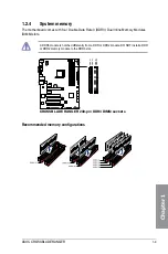
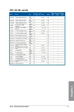
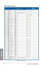
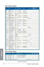
4. DDR3 DIMM slots
1-9
5. Q_Code LED
1-29
6. Power-on button (START)
1-23
7. RESET button
1-23
8. Slow Mode switch
1-26
9. MemOK! button
1-24
10. LN2 Mode Jumper (3-pin LN2_MODE)
1-27
11. Q LEDs (BOOT_DEVICE_LED, VGA_LED, DRAM_LED, CPU_LED)
1-28
12. USB 3.0 connectors (20-1 pin USB3_12)
1-36
13. AMD
®
A88X Serial ATA 6 Gb/s connectors (7-pin SATA6G_1-8 [red])
1-35
14. Hard Disk LED (HD_LED)
1-27
15. BIOS Flashback LED (FLBK_LED)
1-29
16. Direct connector (2-pin DRCT)
1-38
17. System panel connector (20-8 pin PANEL)
1-41
18. KeyBot button (KEYBOT)
1-25
19. KeyBot LED (KEYBOT_LED)
1-28
20. USB 2.0 connectors (10-1 pin USB34; USB56; USB78)
1-37
21. Clear CMOS button (CLR_CMOS)
1-25
22. ROG Extension connector (18-1 pin ROG_EXT)
1-42
23. TPM connector (20-1 pin TPM)
1-42
24. Sonic SoundStage button (SOUNDSTAGE)
1-26
25. Front panel audio connector (10-1 pin AAFP)
1-38
Summary of Contents for Crossblade Ranger
Page 1: ...Motherboard CROSSBLADE RANGER ...
Page 61: ...ASUS CROSSBLADE RANGER 2 5 Chapter 2 To uninstall the APU heatsink and fan assembly 5 3 1 4 2 ...
Page 62: ...2 6 Chapter 2 Basic Installation Chapter 2 1 2 3 To remove a DIMM 2 1 4 DIMM installation B A ...
Page 63: ...ASUS CROSSBLADE RANGER 2 7 Chapter 2 2 1 5 ATX Power connection 1 2 OR ...
Page 64: ...2 8 Chapter 2 Basic Installation Chapter 2 2 1 6 SATA device connection 2 OR 1 ...
Page 72: ...2 16 Chapter 2 Basic Installation Chapter 2 Connect to 7 1 channel Speakers ...
Page 74: ...2 18 Chapter 2 Basic Installation Chapter 2 ...
Page 121: ...ASUS CROSSBLADE RANGER 3 47 Chapter 3 ...
Page 155: ...4 34 Chapter 4 Software support Chapter 4 Function Keys Shortcut ...
Page 165: ...4 44 Chapter 4 Software support Chapter 4 ...
Page 177: ...A 6 Appendices Appendices ...


