background image

2-4

Chapter 2: Basic installation
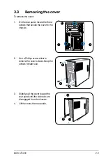
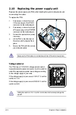
2.4 

Power supply unit

You need to turn over the power supply unit (PSU) section on the side before you 

can install a central processing unit (CPU) and other system components.
To turn over the PSU:

When removing the PSU, ensure to hold or support it firmly. The unit may 

accidentally drop and damage other system components.

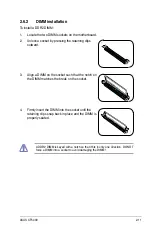
1.  Lay the system chassis on its 

side on a flat and stable surface.

2.  Locate and remove the two 

screws that secures the PSU to 

the chassis. 

3.  Lift the PSU in the direction of 

the arrow to a 90º angle.

Summary of Contents for CT5430

Page 1: ...CT5430 ASUS Desktop PC ...

Page 2: ...CULAR PURPOSE IN NO EVENT SHALL ASUS ITS DIRECTORS OFFICERS EMPLOYEES OR AGENTS BE LIABLE FOR ANY INDIRECT SPECIAL INCIDENTAL OR CONSEQUENTIAL DAMAGES INCLUDING DAMAGES FOR LOSS OF PROFITS LOSS OF BUSINESS LOSS OF USE OR DATA INTERRUPTION OF BUSINESS AND THE LIKE EVEN IF ASUS HAS BEEN ADVISED OF THE POSSIBILITY OF SUCH DAMAGES ARISING FROM ANY DEFECT OR ERROR IN THIS MANUAL OR PRODUCT SPECIFICATIO...

Page 3: ...supply unit 2 4 2 5 CPU installation 2 5 2 5 1 Installing the CPU 2 5 2 5 2 Reinstalling the CPU fan and heatsink assembly 2 7 2 6 Installing a DIMM 2 8 2 6 1 Memory configurations 2 8 2 6 2 DIMM installation 2 11 2 7 Installing an expansion card 2 12 2 7 1 Expansion slots 2 12 2 7 2 Expansion card installation 2 13 2 8 Installing an optical drive 2 14 2 9 Installing a Serial ATA disk drive 2 15 2...

Page 4: ...ollowing measures Reorient or relocate the receiving antenna Increase the separation between the equipment and receiver Connect the equipment to an outlet on a circuit different from that to which the receiver is connected Consult the dealer or an experienced radio TV technician for help Canadian Department of Communications Statement This digital apparatus does not exceed the Class B limits for r...

Page 5: ...p paper clips screws and staples away from connectors slots sockets and circuitry Avoid dust humidity and temperature extremes Do not place the product in any area where it may become wet Place the product on a stable surface When using the product do not block any air inlet outlet in the chassis The maximum environmental temperature is 35ºC If you encounter technical problems with the product con...

Page 6: ...zed This guide contains the following parts 1 Chapter 1 System introduction This chapter gives a general description of ASUS CT5430 The chapter lists the system features including introduction on the front and rear panel and internal components 2 Chapter 2 Basic installation This chapter provides step by step instructions on how to install components in the system 3 Appendix The Appendix includes ...

Page 7: ...n to aid in completing a task Where to find more information Refer to the following sources for additional information and for product and software updates 1 ASUS Websites The ASUS websites worldwide provide updated information on ASUS hardware and software products Refer to the ASUS contact information 2 Optional Documentation Your product package may include optional documentation such as warran...

Page 8: ...g items If any of the items is damaged or missing contact your retailer immediately Item description 1 ASUS CT5430 Desktop PC with ASUS Desktop x 1 Keyboard x 1 Mouse x 1 2 Cable AC power cord x 1 3 Support CD x 1 and Recovery DVD x 1 4 Installation Manual x 1 5 Warranty card x 1 ...

Page 9: ...Chapter 1 System introduction This chapter gives a general description of ASUS CT5430 The chapter lists the system features including introduction on the front and rear panel and internal components ...

Page 10: ...ty the CT5430 is designed for the sophisticated With these and many more the CT5430 definitely delivers the cutting edge technology for your computing and multimedia needs 1 2 Front panel external The front panel includes the system and audio control buttons system LEDs and LED panel 1 Drive door Open this door to access the optical drive 2 Front panel I O cover Open the front panel cover to show ...

Page 11: ...Serial Bus 2 0 USB 2 0 ports are available for connecting USB 2 0 devices such as a mouse printer scanner camera PDA and others 9 Secure Digital MultimediaCard slot This slot is for a Secure Digital MultimediaCard storage card 10 W R LED This LED lights up when data is being read from or written to the card reader 11 Microphone port This Mic pink port connects a microphone 12 Headphone port This p...

Page 12: ...ix channel speaker 18 Microphone port This Microphone pink port connects a microphone In 4 6 channel mode the function of this port becomes Low Frequency Enhanced Output Center 19 VGA port This port connects a VGA monitor 20 PS 2 mouse port This green 6 pin connector is for a PS 2 mouse 21 COM port This port connects a mouse modem or other devices that conforms with serial specification 22 PS 2 ke...

Page 13: ...r In 4 6 channel mode the function of this port becomes Front Speaker Out 29 Coaxial S PDIF Out port This port connects an external audio output device via a coaxial S PIF cable 30 Voltage selector This switch allows you to adjust the system input voltage according to the voltage supply in your area 31 Power connector This connector is for a power cable and plug 32 Power switch This switch allows ...

Page 14: ...d 7 Expansion card slot 8 Power supply unit 1 5 Internal components The illustration below is the internal view of the system when you remove the top cover and the power supply unit The installed components are labeled for your reference Proceed to Chapter 2 for instructions on installing additional system components The illustration shows an open chassis lifted at a 90o angle 1 2 3 4 5 6 7 8 ...

Page 15: ...Chapter 2 This chapter provides step by step instructions on how to install components in the system Basic installation ...

Page 16: ...e that the system is ON in sleep mode or in soft off mode and not powered OFF Unplug the power cable from the power outlet and ensure that the standby power LED is OFF before installing any system component Use a grounded wrist strap or touch a safely grounded object or a metal object such as the power supply case before handling components to avoid damaging them due to static electricity Hold com...

Page 17: ... 4 Lift the cover then set aside 2 Use a Phillips screw driver to remove the cover screws Keep the screws for later use 2 3 Removing the cover To remove the cover 1 On the rear panel locate the three screws that secure the cover to the chassis 1 1 1 REAR S P K LINE IN FRONT MIC IN SIDE S P K C T R BASS 4 3 3 2 2 2 ...

Page 18: ...PU and other system components To turn over the PSU When removing the PSU ensure to hold or support it firmly The unit may accidentally drop and damage other system components 1 Lay the system chassis on its side on a flat and stable surface 2 Locate and remove the two screws that secures the PSU to the chassis 3 Lift the PSU in the direction of the arrow to a 90º angle ...

Page 19: ... the cap after installing the motherboard ASUS will process Return Merchandise Authorization RMA requests only if the motherboard comes with the cap on the LGA775 socket The product warranty does not cover damage to the socket contacts resulting from incorrect CPU installation removal or misplacement loss incorrect removal of the PnP cap 2 5 1 Installing the CPU Before installing the CPU ensure th...

Page 20: ... lever in the direction of the arrow to a 135º angle Load plate PnP cap 4A 4B 3 5 Position the CPU over the socket making sure that the gold triangle is on the bottom left corner of the socket then fit the socket alignment key into the CPU notch Gold triangle mark Alignment key CPU notch 6 Close the load plate A then push the load lever B until it snaps into the retention tab A B ...

Page 21: ...atsink and fan assembly ensure that the Thermal Interface Material is properly applied to the CPU heatsink or CPU before you install the heatsink and fan assembly To install the CPU heatsink and fan 1 Place the heatsink on top of the installed CPU making sure that the four fasteners match the holes on the motherboard 2 Push down two fasteners at a time in a diagonal sequence to secure the heatsink...

Page 22: ...ays install DIMMs with the same CAS latency For optimum compatibility we recommend that you obtain memory modules from the same vendor Due to chipset resource allocation the system may detect less than 2 GB system memory when you installed two 1 GB DDR2 memory This motherboard does not support memory modules made up of 128 Mb chips or double sided x16 memory modules 2 6 1 Memory configurations You...

Page 23: ...KINGMAX KKEA88E4AAK 37 KINGMAX SS KLBC28F A8KE4 1024MB KINGMAX 5MB22D9DCN MICRON DS KLBD48F A8ME4 512MB Apacer AM4B5708GQJS5D N A SS AU512E533C4KBGC 1024MB Apacer AM4B5708GQJS5D N A DS AU01GE533C4KBGC 512MB Super Talent Heat Sink Package N A SS T5UA512C4 1024MB Super Talent Heat Sink Package N A DS T5UB1G8C4 512MB TwinMOS K4T51083QB GCD5 SAMSUNG SS 8D 22JB5 K2T Size Vendor Model Brand SS DS Compon...

Page 24: ...12MB crucial Heat Sink Package N A SS BL6464AA663 8FD 1024MB crucial Heat Sink Package N A DS BL12864AA663 16FD 1024MB crucial Heat Sink Package N A DS BL12864AL664 16FD 1024MB crucial Heat Sink Package N A DS BL12864AA663 16FD2 512MB Apacer AM4B5708GQJS7E0628F APACER SS AU512E667C5KBGC 1024MB Apacer AM4B5708GQJS7E APACER DS AU01GE667C5KBGC 512MB Transcend K4T51083QE SAMSUNG SS TS64MLQ64V6J 1024MB...

Page 25: ... clips outward 3 Align a DIMM on the socket such that the notch on the DIMM matches the break on the socket 4 Firmly insert the DIMM into the socket until the retaining clips snap back in place and the DIMM is properly seated A DDR2 DIMM is keyed with a notch so that it fits in only one direction DO NOT force a DIMM into a socket to avoid damaging the DIMM ...

Page 26: ...pport 2 7 1 Expansion slots Make sure to unplug the power cord before adding or removing expansion cards Failure to do so may cause you physical injury and damage the motherboard PCI Express x16 slot This motherboard supports PCI Express x16 graphic cards that comply with PCI Express specifications The figure shows a graphics card installed on the PCI Express x16 slot The chassis supports PCI Expr...

Page 27: ...firmly 5 Secure the card with one screw 6 Replace the metal braket lock then secure it with one screw Standard interrupt assignments IRQ Standard Function 0 System Timer 1 Keyboard Controller 2 Programmable Interrupt 4 Communications Port COM1 6 Floppy Disk Controller 7 Printer Port LPT1 8 System CMOS Real Time Clock 9 ACPI Mode when used 10 IRQ Holder for PCI Steering 11 IRQ Holder for PCI Steeri...

Page 28: ...nboard USB controller 4 shared Onboard USB 2 0 controller shared Onboard IDE port shared Onboard AC 97 Audio shared Onboard LAN shared Onboard 1394 shared IRQ assignments for this motherboard 2 8 Installing an optical drive The Desktop PC comes with a 5 25 inch drive bays for an optical drive To install an optical drive 1 Place the chassis upright 2 Insert the optical drive to the upper 5 25 in dr...

Page 29: ... the power supply unit 1 2 4 4 4 4 4 2 Connect the SATA signal cable and the power plugs to the connectors at the back of the drive 4 Insert a hard disk drive with the HDD PCB facing the top of the chassis to the tray then secure it with four screws 5 Connect the SATA signal cable to the SATA connector on the motherboard and tighten all the cables with the plastic coils 3 Locate the HDD tray ...

Page 30: ...supply in your area If the voltage supply in your area is 100 127 V set the switch to 115 V If the voltage supply in your area is 200 240 V set the switch to 230 V Setting the switch to 115 V in a 230 V environment will seriously damage the system REAR S P K LINE IN FRONT MIC IN SIDE S P K C T R BASS 1 If necessary connect the 4 pin 12V power plug to the ATX12V connector on the motherboard 2 If ne...

Page 31: ...dge of the cover at least two inches from the front panel cover Fit the cover tabs with the chassis rail and the front panel tabs 3 Lower the rear edge of the cover as shown 4 Push the cover slightly toward the front panel until it fits in place 5 Secure the cover with the three screws you removed earlier 2 3 4 5 ...

Page 32: ...2 18 Chapter 2 Basic installation ...

Page 33: ...Appendix Appendix The Appendix includes the information on recovering your system and troubleshooting ...

Page 34: ...press Enter Wait when the Windows is loading files message appears 4 Select where to install a new system Options are Recover system to a partition This option will delete only the partition you select from below allowing you to keep other partitions and create a new system partition as drive C Select a partition and click NEXT Recover system to entire HD This option will delete all partitions fro...

Page 35: ...vices are compatible with the system Some USB storage devices for example are with different disk drive structure and enter sleep mode easily If the above steps do not solve the problem contact your retailer or perform system recovery using the supplied recovery DVD A 2 Troubleshooting You will lose all your data during the system recovery Make sure that you make a backup of it before recovering t...

Page 36: ...A Appendix ...

Reviews: