


ASUS CUW User’s Manual
21
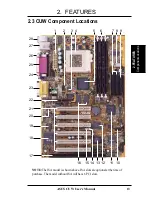
3. HARDWARE SETUP
Motherboard Settings
3. H/W SETUP
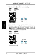
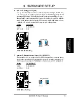
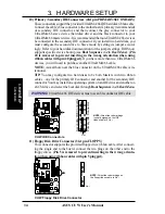
6) Safe Mode Setting (SAFE_MD)
Usually Socket 370 processors have locked frequency multiples. In this case,
there is no way to exceed the specified multiple whether through motherboard
settings or BIOS setup. With unlocked socket processors, exceeding the speci-
fied multiple is possible through BIOS setup. Exceeding the specified multiple
may result in hanging during bootup. If this occurs, enable Safe Mode to force
a multiple of 2 in order to enter BIOS setup to correct the problem.
Setting
SAFE_MD
Normal
[1-2] (default)
Safe Mode
[2-3]
CUW Safe Mode Setting
Normal
(Default)
Safe Mode
1
2
3
1
2
3
SAFE_MD
01
01
01
®
CUW
7) Automatic Timeout Reboot Setting (NO_REBOOT)
The motherboard is set so that when the BIOS detects a hang (timeout) during
bootup, the motherboard will automatically reboot. If rebooting is repeating in-
effectively, set this jumper to No Reboot so that auto-reboot will be disabled.
Setting
NO_REBOOT
Normal
[1-2] (default)
No Reboot
[2-3]
CUW Reboot Setting
Normal
(Default)
No Reboot
1
2
3
1
2
3
NO_REBOOT
01
01
01
®
CUW


