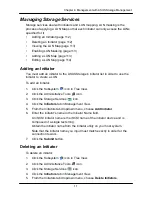
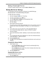
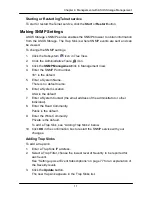
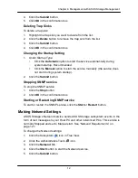
background image

12

Chapter 4: Management with ASUS Storage Management 


If your Netsend and Messenger service settings are correct but the recipient PC 
does not receive event messages, check the recipient PC

’s Firewall settings. 

Refer to your OS documentation for more information. 

Summary of Contents for DS300f

Page 1: ...ASUS Storage DS300f DS300i User Manual Version 1 0 ...

Page 2: ...attempted to ensure the accuracy of the content of this manual it is possible that this document may contain technical inaccuracies typographical or other errors ASUS Technology assumes no liability for any error in this publication and for damages whether direct indirect incidental consequential or otherwise that may result from such error including but not limited to loss of data or profits ASUS...

Page 3: ...ton Weight 6 Safety 6 Environmental 7 Warranty and Support 7 CE Statement 7 FCC Statement 7 KCC Statement 7 Chapter 2 ASUS Storage Installation 9 Unpacking the ASUS Storage 9 Installing the LCD Panel Optional 10 Mounting ASUS Storage in a Rack 12 Installing Disk Drives 15 Number of Drives Required 15 Drive Slot Numbering 15 Installing Your Disk Drives 16 Making Data and Management Connections 18 F...

Page 4: ...tting up with the LCD 45 Making Manual IP Settings 45 Making Automatic IP Settings 46 Creating Disk Arrays with ASUS Storage Management 47 Logging into ASUS Storage Management 47 Choosing a Language 48 Creating Your Logical Drives 49 Logging out of ASUS Storage Management 54 Using ASUS Storage Management over the Internet 54 Chapter 4 Management with ASUS Storage Management 55 Logging into ASUS St...

Page 5: ...ng the Runtime Event Log 67 Clearing the Runtime Event Log 68 Viewing NVRAM Events 68 Saving NVRAM Events 69 Clearing NVRAM Events 69 Viewing Current Background Activities 69 Making Background Activity Settings 69 Running Background Activities 70 Running Media Patrol 71 Running PDM 71 Viewing Scheduled Activities 72 Scheduling an Activity 72 Deleting a Scheduled Activity 73 Viewing Lock Status 73 ...

Page 6: ...e Channel Port Statistics 86 Viewing SFP Information 87 Viewing Fibre Channel Logged in Devices 88 Viewing Fibre Channel Initiators 88 Managing iSCSI Connections 90 Viewing iSCSI Node Information 90 Making iSCSI Node Settings 90 Viewing iSCSI Target Ports 91 Viewing the iSCSI Portal 92 Viewing iSCSI Sessions 92 Working with iSCSI iSNS 93 Working with iSCSI CHAPs 94 Using iSCSI Ping 96 Managing Net...

Page 7: ...ting a NAS File System 109 Viewing the NAS Replication Configuration 109 Setting up NAS Replication 110 Resolving Mount Point Conflicts 111 Managing Storage Services 112 Adding an Initiator 112 Deleting an Initiator 112 Viewing the LUN Map 113 Enabling LUN Masking 113 Adding a LUN Map 113 Editing a LUN Map 114 Managing Software Services 115 Making Email Settings 115 Making SLP Settings 116 Making ...

Page 8: ...sure Information 136 Making Enclosure Settings 137 Viewing FRU VPD Information 137 Checking the Battery 138 Reconditioning a Battery 139 Making Buzzer Settings 139 Managing Physical Drives 140 Viewing a List of Physical Drives 140 Identifying a Physical Drive 140 Making Global Physical Drive Settings 141 Viewing Physical Drive Information 141 Viewing Physical Drive Statistics 142 Making Physical D...

Page 9: ...gical Drive Information 164 Viewing Logical Drive Statistics 165 Making Logical Drive Settings 165 Initializing a Logical Drive 166 Running Redundancy Check 166 Viewing the Logical Drive Check Table 167 Making Logical Drive LUN Settings 168 Creating a LUN Clone 169 Managing Spare Drives 171 Viewing a List of Spare Drives 171 Locating a Spare Drive 171 Creating a Spare Drive 172 Deleting Spare Driv...

Page 10: ...x Language 178 Closing Smart NAS Console 178 ...

Page 11: ...the Backup Event Log 190 Clearing the Backup Event Log 190 Managing Share Folders 191 Creating a Share Folder 191 Opening a Share Folder 191 Viewing a List of Share Folders 191 Changing Share Folder Permissions 192 Changing the Host IP address 192 Deleting a Share Folder 192 Mounting a Share Folder Creating a Network Drive 193 Un mounting a Share Folder Disconnecting a Network Drive 193 Managing U...

Page 12: ...naging the Subsystem 209 Setting an Alias for the Subsystem 209 Running Media Patrol 209 Locking or Unlocking the Subsystem 209 Setting Subsystem Date and Time 210 Setting the Subsystem Time Zone 211 Setting Subsystem NTP 211 Synchronizing the Subsystem NTP Manually 212 Managing the Controller 213 Viewing Controller Information 213 Clearing an Orphan Watermark 213 Making Controller Settings 213 Lo...

Page 13: ...227 Creating a Disk Array Advanced 228 Deleting a Disk Array 229 Viewing Disk Array Information 229 Setting an Alias for a Disk Array 230 Accepting an Incomplete Array 230 Enabling Media Patrol on a Disk Array 231 Enabling PDM on a Disk Array 231 Preparing the Disk Array for Transport 231 Rebuilding a Disk Array 231 Migrating a Disk Array 232 Running PDM 233 Running Transition on a Disk Array 233 ...

Page 14: ...aking Fibre Channel Port Settings 246 Viewing SFP Information 247 Viewing Fibre Channel Port Statistics 248 Viewing Fibre Channel Initiators 249 Adding a Fibre Channel Initiator 249 Managing iSCSI Connections 250 Viewing iSCSI Node Information 250 Making iSCSI Node Settings 250 Viewing iSCSI Target Ports 251 Viewing iSCSI Target Port Statistics 252 Viewing the iSCSI Portal 252 Viewing iSCSI Sessio...

Page 15: ...ement 269 Making Email Settings 269 Making SLP Settings 270 Making Web Server Settings 270 Making Telnet Settings 271 Making SNMP Settings 271 Managing SNMP Trap Sinks 272 Making Netsend Settings 273 Managing Netsend Recipients 273 Flashing through TFTP 275 Viewing Flash Image Information 275 Clearing Statistics 275 Restoring Factory Defaults 276 Shutting Down the Subsystem 277 Shutting down the A...

Page 16: ...ical Drive 291 Managing Disk Arrays 293 Creating a Disk Array Automatic 293 Creating a Disk Array Advanced 294 Deleting a Disk Array 296 Viewing Disk Array Information 296 Locating a Disk Array 297 Creating a Logical Drive 298 Deleting a Logical Drive 299 Viewing Logical Drive Information 300 Locating a a Logical Drive 301 Managing Spare Drives 302 Viewing Spare Drive Information 302 Creating a Sp...

Page 17: ...ng the Memory Module 316 Chapter 9 Technology Background 319 Introduction to RAID 319 RAID 0 Stripe 320 RAID 1 Mirror 321 RAID 1E Enhanced Mirror 322 RAID 3 Block Stripe and Dedicated Parity 323 RAID 5 Block and Parity Stripe 324 RAID 6 Block and Double Parity Stripe 325 RAID 10 Mirror Stripe 326 RAID 30 Striping of Dedicated Parity 327 RAID 50 Striping of Distributed Parity 328 RAID 60 Striping o...

Page 18: ...345 RAID 6 346 RAID 10 346 RAID 30 347 RAID 50 348 RAID 60 348 Ranges of Disk Array Expansion 349 Media Patrol 350 Predictive Data Migration PDM 351 PDM Triggers 351 Transition 352 Example 353 Chapter 10 Troubleshooting 355 ASUS Storage is Beeping 356 LEDs Display Amber or Red 357 Front Panel LEDs 357 Disk Drive LEDs 358 LCD Panel 359 Controller LEDs 359 CLU Reports a Problem 362 Viewing Runtime E...

Page 19: ...ections 393 Network Connections 394 Browser Does Not Connect to ASUS Storage Management 396 Unsaved Data in the Controller Cache 397 ASUS Storage Does Not Boot 397 Chapter 11 Support 399 Frequently Asked Questions 399 Contacting Technical Support 402 Technical Support Services 402 Limited Warranty 403 Disclaimer of other warranties 403 Your Responsibilities 404 Returning the Product For Repair 405...

Page 20: ... command line interface CLI command line utility CLU and embedded ASUS Storage Management software This manual includes a full table of contents index chapter task lists and numerous cross references to help you find the specific information you are looking for Also included are four levels of notices Note A Note provides helpful information such as hints or alternative ways of doing a task Import...

Page 21: ...ower and Status LEDs A defective drive may be replaced without interruption of data availability to the host computer If so configured a hot spare drive will automatically replace a failed drive securing the fault tolerant integrity of the logical drive The self contained hardware based RAID logical drive provides maximum performance in a compact external enclosure Figure 2 ASUS Storage DS300f rea...

Page 22: ...rage appears to the computer s operating system as a standard SCSI drive Disk Drive Support 3 5 x 1 SAS 3 Gb s drives 3 5 x 1 SATA 3 Gb s drives Any combination of SAS and SATA drives in the same system Hot swappable drive bays Staggered physical drive spin up Disk Data Format DDF enables drive roaming between subsystems Multiple global or dedicated hot spare drives with reversion option Controlle...

Page 23: ...ts RAID levels 0 1 1E 3 5 6 10 30 50 and 60 Supports any combination of RAID levels at the same time Configurable stripe sizes 64 KB 128 KB 256 KB 512 KB and 1 MB Multiple global or dedicated hot spare drives with reversion option Up to 256 LUNs per subsystem Up to 32 logical drives LUNs per disk array Out of order logical drive deletion and re creation LUN masking and mapping Extensive SCSI comma...

Page 24: ...ound Activities Bad Sector Mapping Disk array rebuild Media Patrol Online Capacity Expansion OCE Background Activities cont Predictive Data Migration PDM replaces un healthy disk member in array and maintains I O activity during the transition RAID Level Migration RLM Redundancy Check Synchronizing SMART condition pooling Watermarking per BGA in disk and NVRAM Task priority and rate control to bal...

Page 25: ...onal Conditions of running SAS disk drives with one failed cooling fan 5 to 35 C operational 40 to 60 C non operational Relative Humidity 95 percent maximum Vibration Random 0 21 grms 5 500 Hz 30 Mins X Y Z axis Dimensions H x W x D 13 x 45 x 46 cm 5 1 x 17 7 x 18 1 in Net Weight 15 8 kg 34 9 lb without drives 23 8 kg 52 6 lb with 16 drives Assuming 0 5 kg 1 1 lb per drive Carton Dimensions H x W ...

Page 26: ...ivers firmware and compatibility CE Statement Warning This is a class A product In a domestic environment this product may cause radio interference in which case the user may be required to take adequate measures FCC Statement This device complies with Part 15 of the FCC Rules Operation is subject to the following two conditions 1 this device may not cause harmful interference and 2 this device mu...

Page 27: ...8 Chapter 1 Introduction to ASUS Storage ...

Page 28: ...DB9 serial data cable Screws for disk drives 70 pieces 1 5m 4 9 ft Power cords 2 CD with SNMP files User Manual and Quick Start Guide in PDF format A Battery Backup Unit BBU is optional on the ASUS Storage subsystem In the event of a power failure the BBU powers the controller cache to preserve any data it contains Warning This is a Class A product In a domestic environment this product may cause ...

Page 29: ...nect or disconnect the LCD panel You must install the LCD panel before you mount the ASUS Storage subsystem in a rack The LCD panel mounts to the left ear of the ASUS Storage enclosure 1 Align the connector on the left bracket of the ASUS Storage enclosure to the connector on the back of the LCD panel as shown in Figure 1 Figure 1 Align the connectors on the enclosure and the LCD panel Connector o...

Page 30: ...rage Installation Tighten the screws to secure the LCD panel to the bracket Figure 2 Attach the LCD panel to the ASUS Storage enclosure The LCD screen activates when the ASUS Storage boots See Connecting the Power on page 33 ...

Page 31: ...nging components Mount the rails to the rack using the appropriate screws and flange nuts fully tightened at each end of the rail Do not load the rails unless they are installed with screws as instructed The rails that ship with the ASUS Storage unit are designed to safely support that ASUS Storage unit when properly installed Additional loading on the rails is at the customer s risk ASUSTek COMPU...

Page 32: ...se no adjustment screws 3 Attach the mounting rail assemblies to the outside of the rack posts using the attaching screws and flange nuts from your rack system Be sure the front rail support is on the bottom facing inward The alignment pins fit into the rack holes above and below the attaching screws Use the attaching screws and flange nuts from your rack system Tighten the screws and flange nuts ...

Page 33: ...diagram Rack front post Alignment pins two on each flange Rack rear post Front rail Rear rail Support for subsystem Inside of post Rail attaching screws not included Inside of post Note that only the front rail has a support for the subsystem This completes rack mounting ...

Page 34: ...el Level Number of Drives Level Number of Drives RAID 0 1 or more RAID 6 4 to 32 RAID 1 2 only RAID 10 4 or more RAID 1E 2 or more RAID 30 6 or more RAID 3 3 to 32 RAID 50 6 or more RAID 5 3 to 32 RAID 60 8 or more A JBOD expansion unit may be required Must be an even number of drives Drive Slot Numbering You can install any suitable disk drive into any slot in the enclosure The diagram below show...

Page 35: ...ve a disk drive carrier 2 Carefully lay the disk drive into the drive carrier at the front so that the screw holes on the sides line up See page 17 Figure 6 3 Insert the screws through the holes in the drive carrier and into the sides of the disk drive Install only the counter sink screws supplied with the ASUS Storage Install four screws per drive Snug each screw Be careful not to over tighten 4 ...

Page 36: ...e mounted in a drive carrier Disk drive mounting screw mounting screw This completes disk drive installation Caution ASUS Storage supports disk drive hot swapping To avoid hand contact with an electrical hazard do not remove more than one drive carrier a time ...

Page 37: ...iple RAID subsystems Cascading is planned for a future release Fibre Channel Direct Attached Storage DAS This arrangement requires A Fibre Channel FC interface card in the Host PC At least one FC transceiver for each ASUS Storage subsystem A network interface card NIC in the Host PC A standard network switch Note ASUS Storage Fibre Channel subsystems also have two 2 Ethernet RJ45 iSCSI Port connec...

Page 38: ...r standard NIC in the Host PC Attach the other end of the Ethernet cable to one of the ports on the standard network switch See page 20 Figure 8 2 Attach one end of an Ethernet cable to one of the ports on the standard network switch Attach the other end of the Ethernet cable to the Management Port on the ASUS Storage DS300f subsystem If you have multiple DS300f subsystems Host PCs or Servers repe...

Page 39: ...apter 2 ASUS Storage Installation Figure 8 FC DAS data and management connections Host PC or Server Network Switch Management Cables ASUS Storage DS300f NIC FC card Data Cable Management Port FC Data Ports 2 ...

Page 40: ... an FC transceiver into the FC data port on the ASUS Storage controller See page 23 Figure 9 2 Connect the FC transceiver on the ASUS Storage subsystem to the FC switch 3 Connect the FC switch to the FC HBA card in the Host PC or Server If you have multiple ASUS Storage subsystems Host PCs or Servers repeat steps 1 and 2 as required See also SAS JBOD Expansion on page 30 Management Path The ASUS S...

Page 41: ...Storage Installation Attach the other end of the Ethernet cable to the Management Port on the ASUS Storage DS300f subsystem If you have multiple ASUS Storage subsystems Host PCs or Servers repeat steps 1 and 2 as required ...

Page 42: ...nstallation Figure 9 FC SAN data and management connections NIC FC card Management Cables Data Cables Host PCs or Servers NIC FC card Network Switch FC Switch ASUS Storage DS300f ASUS Storage DS300f Management Port FC Data Ports 2 ...

Page 43: ...nd of the Ethernet cable to one of the four iSCSI ports on the ASUS Storage DS300i controller If you have multiple ASUS Storage DS300i subsystems Host PCs or Servers repeat steps 1 and 2 as required See also SAS JBOD Expansion on page 30 Configuring a Management Path The ASUS Storage DS300i controller has one 1 Ethernet RJ 45 Management Port connector See page 25 Figure 10 To establish the managem...

Page 44: ...hapter 2 ASUS Storage Installation Figure 10 ASUS Storage D300i data and management ports Management Port iSCSI Data Port 3 iSCSI Data Port 2 iSCSI Data Port 1 iSCSI Data Port 4 SAS Expansion Port to DS300j ...

Page 45: ... Storage Installation Figure 11 iSCSI DAS data and management connections Standard NIC GbE NIC Host PC or Server Standard Network Switch Management Cables Data Cable ASUS Storage DS300i Management Port iSCSI Data Ports 4 ...

Page 46: ...net RJ45 iSCSI Port connectors See page 25 Figure 10 To establish the data path 1 Attach one end of an Ethernet cable to the GbE iSCSI NIC in the Host PC Attach the other end of the Ethernet cable to one of the ports on the GbE network switch See page 29 Figure 12 If you have multiple ASUS Storage DS300i subsystems Host PCs or Servers repeat steps 1 and 2 as required 2 Attach one end of an Etherne...

Page 47: ...andard NIC in the Host PC Attach the other end of the Ethernet cable to one of the ports on the standard network switch See page 29 Figure 12 2 Attach one end of an Ethernet cable to one of the ports on the standard network switch Attach the other end of the Ethernet cable to the Management Port on the ASUS Storage DS300i subsystem See page 29 Figure 12 If you have multiple ASUS Storage DS300i sub...

Page 48: ...iSCSI SAN data and management connections Standard NIC GbE NIC Standard NIC GbE NIC Host PCs or Servers Standard Network Switch Management Cables Data Cables GbE Network Switch ASUS Storage DS300i Management Port iSCSI Data Ports 4 ASUS Storage DS300i ...

Page 49: ...o the SAS IN Port on the ASUS DS300j expansion units If you have another ASUS DS300j expansion unit attach one end of the SFF 8088 to SFF 8088 SAS cable to the SAS OUT Port of the first ASUS DS300j to the SAS IN Port of the second ASUS DS300j Important ASUS Storage DS300j expansion units have one SAS IN port and one SAS OUT port If you connect them incorrectly the ASUS Storage does not recognize t...

Page 50: ...S Storage DS300j expansion data connections SAS Expansion Port ASUS Storage DS300i ASUS DS300j SAS data cable SAS OUT Port SAS IN Port ASUS DS300j After you complete your data and management connection go to Setting Up Serial Cable Connections on page 32 ...

Page 51: ... to DB9 serial data cable Figure 14 Serial connector on a DS300f controller RJ11 Serial Connector Figure 15 Serial connector on a DA300i controller RJ11 Serial Connector To set up a serial cable connection 1 Attach the RJ11 end of the serial data cable to the RJ11 serial connector on the controller 2 Attach the DB9 end of the serial data cable to a serial port on the Host PC or Server This complet...

Page 52: ... boot up is finished and the ASUS Storage DS300f or DS300i subsystem is functioning normally Power Global Enclosure Status and Global RAID Status LEDs display green continuously Controller Activity LED flashes green when there is controller activity System Heartbeat LED blinks green seven times in three seconds goes dark for six seconds then repeats the pattern Figure 16 ASUS Storage subsystem fro...

Page 53: ...ller status LEDs display green continuously Ethernet LEDs display green or flash depending on your network connection The FC iSCSI SAS and Expansion LEDs display green or flash during port activity Figure 17 ASUS Storage DS300f controller LEDs Controller Status Fan 2 Fan 1 Battery Dirty Cache USB 2 USB 1 iSCSI 1 2 FC Ports 1 2 JBOD Expansion Fan 1 Fan 2 ...

Page 54: ...ach Drive Carrier They report the presence of a disk drive activity of the drive and the drive s current condition Figure 19 ASUS Storage drive carrier LEDs If there is a disk drive in the carrier the Power Activity LED displays Green If not the Power Activity LED remains dark The Power Activity LED flashes during drive activity The Disk Status LED displays Green when a drive is configured Disk St...

Page 55: ...ables you to manage your ASUS Storage subsystem when it is configured as Network Attached Storage NAS The NAS option requires An iSCSI SAN data connection see page 27 Logical drives configured for NAS see page 51 To install Smart NAS Console 1 Open the software CD find the Smart NAS Console install icon right and drag it to your PC s desktop 2 Double click the Smart NAS Console Install icon to beg...

Page 56: ...ave an Internet connection Thank you for registering 8 In the second Installation Complete screen choose whether you want to restart your PC now When you restart your PC Smart NAS Console runs automatically Then click the Finish button For more information see Chapter 5 Smart NAS Console on page 177 and Appendix A Setting up NAS Network Drives on page 407 ...

Page 57: ...3 8 Chapter 2 ASUS Storage Installation ...

Page 58: ...as Microsoft HyperTerminal This procedure uses the serial cable connection you made in Chapter 2 page 32 You must use the CLI or CLU to assign an IP address to the ASUS Storage to enable a network connection for ASUS Storage Management 1 Change your terminal emulation program settings to match the following specifications Bits per second 115200 Data bits 8 Parity None Stop bits 1 Flow control none...

Page 59: ... server from assigning a new IP address when the ASUS Storage restarts with the result that users can no longer log in To access the MAC address for ASUS Storage s management port 1 At the administrator cli prompt type menu and press Enter The CLU main menu appears 2 In the CLU Main Menu highlight Network Management and press Enter then highlight the management port and press Enter Figure 1 Viewin...

Page 60: ...ill be different If you prefer to let your DHCP server assign the IP address type the following string then press Enter administrator cli net a mod t mgmt s dhcp enable 3 To verify the settings type net and press Enter administrator cli net CId Port Type IP Mask Gateway Link 1 1 Mgmt 192 168 10 85 255 255 255 0 192 168 10 1 Up 1 1 iSCSI 10 0 0 2 0 0 0 0 0 0 0 0 Down 1 2 iSCSI 10 0 0 3 0 0 0 0 0 0 ...

Page 61: ... Gateway Link 1 1 Mgmt 192 168 10 85 255 255 255 0 192 168 10 1 Up 1 1 iSCSI 192 168 10 88 255 255 255 0 192 168 10 1 Up 1 2 iSCSI 10 0 0 3 0 0 0 0 0 0 0 0 Down 1 3 iSCSI 10 0 0 4 0 0 0 0 0 0 0 0 Down 1 4 iSCSI 10 0 0 5 0 0 0 0 0 0 0 0 Down 6 Repeat steps 3 and 4 to set the other iSCSI ports Use p 2 p 3 or p 4 in place of p 1 ...

Page 62: ... date and time To make date and time settings 1 Press the arrow keys to highlight System Date 2 Press the backspace key to erase the current date 3 Type the new date 4 Follow the same procedure to set the System Time 5 Press Ctrl A to save these settings and move to the Management Port configuration screen Making Manual IP Settings To make Management Port and iSCSI Port settings manually 1 Press t...

Page 63: ...configuration screen Configuring the RAID You can configure your RAID arrays and logical drives using the CLU at this time However those actions are described in Creating Disk Arrays with ASUS Storage Management page 47 ASUS suggests that you highlight Skip the Step and Finish and press Enter Then create your disk array using WebPAM PRO Viewing IP Address and Settings To view the current IP addres...

Page 64: ...Press the or button and the display says IP Address 4 Press the button to make a change The current IP Address displays with the cursor under the first extreme left digit 5 Press the button to increment and the button decrement Press the button to move left and the button move right To set an IP address with double or single digit octets for example 192 168 1 50 type zeros as placeholders 192 168 ...

Page 65: ... until the display says Management Port 2 Press the button and the display says Link Status Up If it says Link Status Down reconnect to the network before preceding 3 Press the or button and the display says DHCP Disable 4 Press the button to make a change 5 Press the button to Enable 6 Press the button to confirm The display shows the new IP address set by the DHCP server This completes the Manag...

Page 66: ...sk 7 see page 41 Note that the IP address shown below is only an example The IP address you type into your browser will be different Regular Connection ASUS Storage Management uses an HTTP connection http Enter the ASUS Storage s IP address 192 168 10 85 Together your entry looks like this http 192 168 10 85 Secure Connection ASUS Storage Management uses a secure HTTP connection https Enter the AS...

Page 67: ... appear See page 49 Figure 6 Note Make a Bookmark Firefox or set a Favorite Internet Explorer of the Login Screen so you can access it easily next time Choosing a Language ASUS Storage Management displays in English German French Italian Spanish Russian Japanese Chinese Traditional Chinese Simple and Korean 1 Click Language on the ASUS Storage Management banner The language list appears in the Hea...

Page 68: ...are drive for all RAID levels except RAID 0 if at least four unconfigured physical drives are available See page 50 Express You choose the parameters for a new disk array by specifying the characteristics you want You can create multiple logical drives at the same time however they will all be identical You can choose to make a hot spare drive for all RAID levels except RAID 0 if at least four unc...

Page 69: ...u choose the Express option a set of characteristics and options appears on the screen 1 Check the boxes to choose any one or a combination of Redundancy The array will remain available if a physical drive fails Capacity The greatest possible amount of data capacity Performance The highest possible read write speed Spare Drive A hot spare drive is created when you choose Redundancy Spare Drive and...

Page 70: ...ew disk array appears in the Disk Array List on the Information tab Advanced Note For an explanation of the parameters under the Advanced option see Chapter 9 Technology Background on page 319 When you choose the Advanced option the Step 1 Disk Array Creation screen displays Step 1 Disk Array Creation 1 Optional Enter a name for the disk array in the field provided Maximum of 31 characters letters...

Page 71: ...city of the first logical drive in your new disk array If you specify less than disk array s maximum capacity the remaining capacity is available for additional logical drives that you can create now or later 6 For the following items accept the default or choose a new value from the dropdown menu Stripe size 128 KB is the default 64 KB 128 KB 256 KB 512 KB and 1 MB are available Sector size 512 B...

Page 72: ...age Management Close your browser window Click Logout on the ASUS Storage Management banner Figure 7 Clicking Logout on the ASUS Storage Management banner Clicking Logout brings you back to the Login Screen See page 30 After logging out you must enter your user name and password in order to log in again Using ASUS Storage Management over the Internet The above instructions cover connections betwee...

Page 73: ...54 Chapter 3 ASUS Storage Setup ...

Page 74: ...e User Database page 123 Importing a User Database page 123 Importing a Configuration Script page 124 Updating the Firmware page 125 Viewing Flash Image Information page 125 Restoring Factory Defaults page 126 Clearing Statistics page 126 Shutting Down the Subsystem page 127 Starting Up After Shutdown page 129 Restarting the Subsystem page 130 Managing the Controller page 131 Managing Enclosures p...

Page 75: ...ion http Enter the ASUS Storage s IP address 192 168 10 85 Together your entry looks like this http 192 168 10 85 Secure Connection ASUS Storage Management uses a secure HTTP connection https Enter the ASUS Storage s IP address 192 168 10 85 Together your entry looks like this https 192 168 10 85 Note Whether you select a regular or a secure connection your login to ASUS Storage Management and you...

Page 76: ...Note Make a Bookmark Firefox or set a Favorite Internet Explorer of the Login Screen so you can access it easily next time Choosing a Language ASUS Storage Management displays in English German French Italian Spanish Russian Japanese Chinese Traditional Chinese Simple and Korean 1 Click Language on the ASUS Storage Management banner The language list appears in the Header 2 Click on the language y...

Page 77: ...ge Management Figure 2 Clicking Language on the ASUS Storage Management banner Perusing the Interface ASUS Storage Management is browser based RAID management software with a graphic user interface Figure 3 ASUS Storage Management interface ...

Page 78: ...Working with the Storage Network on page 63 Contact Us Click Contact Us for a list of contact information including Technical Support Also see Contacting Technical Support on page 402 Logout To log out of ASUS Storage Management see page 62 Help Click Help in the Header to access the main online help menu About Click About in the Header to display the ASUS Storage Management software version and b...

Page 79: ...60 Chapter 4 Management with ASUS Storage Management Figure 4 ASUS Storage Management Tree View Name of Logged in user Subsystem IP address and ASUS storage model Physical Drives in this Enclosure ...

Page 80: ...he event frame events are listed and sorted by Item Number A consecutive decimal number assigned to a specific event Device Battery controller logical drive physical drive port etc Event ID The hexadecimal number that identifies the specific type of event Severity Information Warning Minor Major Critical and Fatal The severity level is user specified See Setting up User Event Subscriptions on page...

Page 81: ...out of ASUS Storage Management Close your browser window Click Logout on the ASUS Storage Management banner Figure 5 Clicking Logout on the ASUS Storage Management banner Clicking Logout brings you back to the Login Screen See page 57 After logging out you must enter your user name and password in order to log in again ...

Page 82: ...stems the Storage Network 1 Click Storage Network in the Header 2 Click the Show Network Subsystems popup option The list will show all subsystems the network at the time the GUI was launched Updating the List of Subsystems To update the list of the ASUS Storage subsystems on the Storage Network Click the Discover button at the bottom of the subsystem list Logging into a Subsystem To log into any ...

Page 83: ... Event Log page 67 Saving the Runtime Event Log page 67 Clearing the Runtime Event Log page 68 Viewing NVRAM Events page 68 Saving NVRAM Events page 69 Clearing NVRAM Events page 69 Viewing Current Background Activities page 69 Making Background Activity Settings page 69 Running Background Activities page 70 Running Media Patrol page 71 Running PDM page 71 Viewing Scheduled Activities page 72 Sche...

Page 84: ...To set an alias for this subsystem 1 In Tree View click the Subsystem icon 2 In Management View click the Settings tab 3 Enter a name into the Alias field Maximum of 48 characters Use letters numbers space between words and underscore 4 Click the Submit button Setting Subsystem Date and Time To set a Date and Time for this subsystem 1 In Tree View click the Subsystem icon 2 In Management View clic...

Page 85: ...ee View click the Subsystem icon 2 In Management View from the Settings tab dropdown menu choose NTP Management 3 Check the NTP Service box to enable the NTP service 4 Enter the URLs for NTP servers in the fields provided One URL is required Additional URLs are optional 5 From the Time Zone dropdown menu choose your time zone 6 If your location observes Daylight Saving Time Check the Daylight Savi...

Page 86: ...imal number that identifies the specific type of event Severity Information Warning Minor Major Critical and Fatal The severity level is user specified See Setting up User Event Subscriptions on page 77 Time Time and date of the occurrence Description A brief description of the event 3 Click the link at the top of the column by which you want to sort the events After you click the item a triangle ...

Page 87: ... 2 In Management View click the Events tab dropdown menu and choose System Events in NVRAM Events are displayed by Item Number A consecutive decimal number assigned to a specific event Device Battery controller logical drive physical drive port etc Event ID The hexadecimal number that identifies the specific type of event Severity Information Warning Minor Major Critical and Fatal The severity lev...

Page 88: ...g 1 In Tree View click the Subsystem icon 2 In Management View click the Events tab dropdown menu and choose System Events in NVRAM 3 Click the Clear Event Log button 4 In the Confirmation dialog box type confirm and click the OK button Viewing Current Background Activities To view the current background activities 1 In Tree View click the Subsystem icon 2 In Management View click the Background A...

Page 89: ...e resources to activity fewer to data read write 4 Highlight the following PDM trigger settings and type a value into the corresponding field Reassigned Block Threshold 1 to 512 blocks Error Block Threshold 1 to 1024 blocks 5 Check to enable or uncheck to disable the following functions Media Patrol Checks the magnetic media on physical drives Auto Rebuild If there is a spare drive of adequate cap...

Page 90: ...ck the Subsystem icon 2 From the dropdown menu on the Background Activities tab choose Start Media Patrol 3 In the next screen click the Start button Running PDM Predictive Data Migration PDM migrates data from the suspect physical drive to a spare disk drive similar to Rebuilding But unlike Rebuilding PDM acts before the disk drive fails and your Logical Drive goes Critical You an also run PDM on...

Page 91: ... the Scheduler dialog box check the Enable This Schedule box 4 Select a start time 24 hour clock 5 Select a Recurrence Pattern Daily Enter the number of days between events Weekly Enter the number of weeks between events and choose which days of the week Monthly Choose a calendar day of the month 1 31 If you choose a higher number than there are days in the current month the actual start date will...

Page 92: ...r this subsystem 1 Click the Subsystem icon Tree View 2 From the dropdown menu on the Scheduler tab choose Delete Schedules 3 Check the box to the left of the schedule you want to delete 4 Click the Submit button Viewing Lock Status The lock prevents other sessions including by the same user from making a configuration change to the controller until the lock expires or a forced unlock is done To v...

Page 93: ...til the lock expires or a forced unlock is done Renewing the lock extends the period of time the controller remains locked To renew an existing lock for this subsystem 1 Click the Subsystem icon Tree View 2 Click the Lock tab in Management View 3 Click the Renew option 4 Enter a time interval between 1 and 1440 minutes one day that you want the lock to stay active The renew time replaces the previ...

Page 94: ... with ASUS Storage Management If you are the User who set the lock click the Unlock option If another User set the lock and you are a Super User click the Unlock option and check the Force Unlock box 3 Click the Submit button ...

Page 95: ...status access privileges display name and email address 1 Click the Subsystem icon in Tree View 2 Click the Administrative Tools icon 3 Click the User Management icon The Information tab appears in Management View Making User Settings To change settings of other users 1 Log into ASUS Storage Management as the Administrator or a Super User 2 Click the Subsystem icon in Tree View 3 Click the Adminis...

Page 96: ... Click the Submit button Setting up User Event Subscriptions An event subscription enables a user to receive email messages about events taking place in the ASUS Storage subsystem To make or change user event subscriptions 1 Click the Subsystem icon in Tree View 2 Click the Administrative Tools icon 3 Click the User Management icon 4 Click the Event Subscription tab in Management View 5 Check the ...

Page 97: ...n in Tree View 3 Click the Administrative Tools icon 4 Click the User Management icon 5 In the list of users click the link of the user whose settings you want to change The Settings screen for the selected user displays 6 Click the Password tab in Management View 7 Enter a new password of 1 to 31 characters no spaces in the New Password field 8 Enter the new password in the Retype Password field ...

Page 98: ...ent with the User Name and leave the password field blank 8 Enter a display name in the Display Name field A display name is optional 9 Enter the user s email address in the Email Address field An email address is required in order to receive email event notification 10 Select a privilege level from the Privilege dropdown menu For definitions of each privilege level see the List of User Privileges...

Page 99: ... Management icon 5 Click the Delete tab in Management View 6 Check the box to the left of the user you want to delete 7 Click the Submit button 8 Click OK in the confirmation box Viewing User Sessions To view the current sessions 1 Click the Subsystem icon in Tree View 2 Click the Administrative Tools icon 3 Click the User Management icon 4 Click the Sessions tab in Management View Logging out Oth...

Page 100: ...tic IP Address on page 40 To make changes to the Management Port settings 1 Click the Subsystem icon in Tree View 2 Click the Administrative Tools icon 3 Click the Network Management icon 4 Click the Port Configuration link in Management View 5 To enable DHCP check the DHCP box When DHCP is NOT enabled enter Primary IP address Primary subnet mask Default gateway IP address Enter a primary DNS serv...

Page 101: ...Submit button Creating a Link Aggregation Entry Link aggregation combines multiple network ports in parallel to increase link speed and to provide redundancy for high availability This feature enables you to aggregate the iSCSI data ports on your subsystem To create a link aggregation entry 1 Click the Subsystem icon in Tree View 2 Click the Administrative Tools icon 3 Click the Network Management...

Page 102: ... icon 4 In Management View click the Link Aggregation tab 5 Click the ID link of the link aggregation you want to change 6 From the Master Port dropdown menu choose an iSCSI port number 7 From the Slave Port dropdown menu choose another iSCSI port number 8 Click the Submit button Deleting a Link Aggregation Entry To delete a link aggregation entry 1 Click the Subsystem icon in Tree View 2 Click th...

Page 103: ...inistrative Tools icon 3 Click the Fibre Channel Management icon 4 Click the Node tab in Management View The current node data port settings the Controller are shown including WWNN World Wide Node Name Supported Features Class of service Maximum Frame Size 2048 bits Supported Speeds 8 Gb s 4 Gb s or 2 Gb s Viewing Fibre Channel Port Settings To view the current Fibre Channel port settings 1 Click ...

Page 104: ...ick the Subsystem icon in Tree View 2 Click the Administrative Tools icon 3 Click the Fibre Channel Management icon 4 Click the Port tab in Management View 5 Click the Port1 or Port2 link in Management View 6 Make the settings appropriate to your system See Port Setting Information on page 85 Configured Link Speed 8 Gb s 4 Gb s 2 Gb s or Auto self setting Configured Topology N Port Point to Point ...

Page 105: ...e Channel ports 1 Click the Subsystem icon in Tree View 2 Click the Administrative Tools icon 3 Click the Fibre Channel Management icon 4 Click the Statistic tab in Management View The statistics for all Fibre Channel ports are shown Property Definitions Definitions of the properties for which statistical information is reported appears in the list below Time Since Last Reset Time in minutes since...

Page 106: ... Number of times a loss of sync has occurred since last reset Primitive Sequence Error Count An ordered set transmitted repeatedly and used to establish and maintain a link LR LRR NOS and OLS are primitive sequences used to establish an active link in a connection between two N_Ports or an N_Port and an F_Port LIP LPB and LPE are primitive sequences used in the Arbitrated Loop topology for initial...

Page 107: ...dministrative Tools icon 3 Click the Fibre Channel Management icon 4 Click the Logged In Device tab in Management View One of the devices in the list will be the port itself If there is no other device this notification will appear There is no logged in device If a Fibre Channel switch is attached it will also appear in this list Viewing Fibre Channel Initiators You must add an initiator to the AS...

Page 108: ...add an initiator to the ASUS Storage s initiator list 1 Check the box to the left of the initiator 2 Click the Add to Initiator List button The initiator appears under Storage Services See page 112 You can then use the initiator to create a LUN See Adding a LUN Map on page 113 ...

Page 109: ...ode Information The iSCSI node is the ASUS Storage DS300i controller The iSCSI Node has four ports See Making Data and Management Connections on page 18 for information about how these ports are physically connected to the Host PC To view information about the iSCSI node 1 Click the Subsystem icon in Tree View 2 Click the Administrative Tools icon 3 Click the iSCSI Management icon Node information...

Page 110: ...te below Enable Data Digest Enables use of a Data Digest CRC See note below Enable Uni directional CHAP Authentication Enables Challenge Handshake Authentication Protocol Enable Bi directional CHAP Authentication 7 Click the Submit button Notes Header Digest and Data Digest work best with initiators equipped with a TCP Offload Engine TOE Refer to your iSCSI HBA user manual for more information For...

Page 111: ...n in Tree View 2 Click the Administrative Tools icon 3 Click the iSCSI Management icon 4 Click the Portals tab in Management View The Portals tab displays the following information Portal ID 0 to 34 IP Address IP address of the port Associated Type iSCSI IF Name Port number TCP port number 3260 is the default Viewing iSCSI Sessions To view a list of the current iSCSI sessions 1 Click the Subsystem...

Page 112: ...e automated discovery management and configuration of iSCSI devices on a TCP IP network View Settings To view iSNS settings 1 Click the Subsystem icon in Tree View 2 Click the Administrative Tools icon 3 Click the iSCSI Management icon 4 Click the iSNS tab in Management View iSNS information includes iSNS status Enabled or disabled ESI status Enabled or disabled See Note below Get iSNS IP through ...

Page 113: ...et or password The peer concatenates the sequence number the random value and the secret and calculates a hash using a one way hash algorithm such as MD5 The peer sends the hash value back to the authenticator which in turn builds that same string on its side calculates the hash and compares the result with the value received from the peer If the values match the peer is authenticated The authenti...

Page 114: ... to peer is one way authentication Local is bi directional authentication 9 Click the Submit button Editing CHAPs To edit a CHAP 1 Click the Subsystem icon in Tree View 2 Click the Administrative Tools icon 3 Click the iSCSI Management icon 4 Click the CHAP tab in Management View 5 Click the CHAP name link 6 Make changes as required Highlight the current name press the backspace key to erase it th...

Page 115: ...he Submit button Using iSCSI Ping You can send a ping through ASUS Storage s iSCSI data ports to verify a network connection To send a ping 1 Click the Subsystem icon in Tree View 2 Click the Administrative Tools icon 3 Click the iSCSI Management icon 4 Click the Ping tab in Management View 5 Enter the IP address you want to ping in the IP Address field 6 Choose an iSCSI data port from the Ping Th...

Page 116: ...102 Viewing Protocol Status page 102 Making Windows Protocol Settings page 102 Making FTP Protocol Settings page 104 Making UNIX and Linux Protocol Settings page 104 Viewing the Share Folders List page 105 Creating a Share Folder page 105 Modifying a Share Folder page 106 Deleting a Share Folder page 106 Making Windows and FTP Sharing Settings page 107 Making UNIX Linux Sharing Settings page 107 V...

Page 117: ... in Management View 6 Enter a user name of 1 to 16 characters no spaces in the User Name field 7 Enter a password of 1 to 16 characters no spaces in the New Password field 8 Enter the password again in the Retype Password field 9 Click the Submit button 10 Click the OK button to acknowledge The new user appears under the Information tab Important By default all users have full Read Write access to...

Page 118: ...S Users To delete a NAS user 1 Click the Subsystem icon in Tree View 2 Click the Administrative Tools icon 3 Click the NAS icon 4 Click the NAS User Management icon 5 Click the Delete User tab in Management View 6 Click the Option button beside the user you want to delete 7 Click the Submit button 8 Click the OK button to confirm 9 Click the OK button to acknowledge Viewing the List of NAS Groups ...

Page 119: ...ge 100 Deleting a NAS Group To delete a NAS Group 1 Click the Subsystem icon in Tree View 2 Click the Administrative Tools icon 3 Click the NAS icon 4 Click the NAS User Group Management icon 5 Click the Delete tab in Management View 6 Click the Option button beside the Group you want to delete 7 Click the OK button to confirm 8 Click the OK button to acknowledge The Group is deleted under the Inf...

Page 120: ...AS User Group Management icon 5 Click the Group Members tab in Management View 6 From the dropdown menu choose the Group from which you want to delete a User 7 From the Members list highlight a User to delete from the Group and click the button The User moves to the Users list 8 Click the OK button to acknowledge Viewing Quota Information To access Quota information 1 Click the Subsystem icon in T...

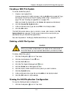
Page 121: ...nagement View 6 Choose a NAS volume from the Volume dropdown menu 7 Choose an Account Group Names are preceded by an character User 8 Click the Limited Quota option and enter a value in the MB field Sets the amount of data storage in megabytes 9 Click the Submit button Viewing Protocol Status Protocols enable NAS service on your Host or PC s operating system To view the Protocol status 1 Click the...

Page 122: ...ycle Bin to remove them from the ASUS Storage Uses more space Disabled Default Deleted files are immediately removed from the ASUS Storage Saves space but has no change of file recovery Accept the current Workgroup Name or type a new name into the field An Active Directory AD Domain A Workgroup If you chose and AD Domain enter the following information in the fields provided Domain Name Domain Con...

Page 123: ...535 Be sure the port numbers you enter are enabled on your firewall and server 8 Click the Submit button 9 Click the OK button to acknowledge Making UNIX and Linux Protocol Settings Protocols are disabled by default Enable the protocols appropriate for your Hosts or PCs To make UNIX or Linux Protocol settings 1 Click the Subsystem icon in Tree View 2 Click the Administrative Tools icon 3 Click the...

Page 124: ...rative Tools icon 3 Click the NAS icon 4 Click the File Sharing icon Creating a Share Folder Share folders are created on Volumes Volumes are created when you create a NAS file system on a new logical drive See Creating a NAS File System on page 109 To create a Share Folder 1 Click the Subsystem icon in Tree View 6 Do the following actions as required Choose the Volume you want from the dropdown m...

Page 125: ...nt from the dropdown menu Choose the Folder you want from the dropdown menu Type a new name for the share folder in the Folder name field Check the box to enable each service for the share folder The choices are Windows Unix Linux and FTP All services are disabled by default 7 Click the Submit button 8 Click the OK button to confirm Deleting a Share Folder To delete a Share Folder 1 Click the Subs...

Page 126: ...enu choose the folder you want modify Check the boxes for the protocols you want for this folder Windows FTP In the Permission list click the option button for one of the following permissions for each group and user Deny Access Visible only cannot open Read Only Read and Write Default 7 Click the Submit button 8 Click the OK button to acknowledge Making UNIX Linux Sharing Settings UNIX and Linux ...

Page 127: ...bsystem icon in Tree View 2 Click the Administrative Tools icon 3 Click the NAS icon 4 Click the File System Management icon Rebuilding a NAS File System Typically the first indication of a problem with the NAS file system is when your network drive becomes unavailable Rebuilding the file system does NOT cause data loss To check and rebuild a file system 1 Click the Subsystem icon in Tree View 2 C...

Page 128: ...stem name is the mount point you specified when you created the logical drive See also Appendix A Setting up NAS Network Drives on page 407 Deleting a NAS File System Caution When you delete a share folder you delete all the data saved in the folder Back up any important data before you delete a folder To delete a NAS file system 1 Click the Subsystem icon in Tree View 2 Click the Administrative T...

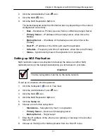
Page 129: ...atus Synchronizing means the replication is in progress Setting up NAS Replication NAS replication uses one subsystem to backup the data on another NAS replication works in the background allowing you full access to your data Important The two subsystems must be on the same network To set up or schedule a NAS replication 1 Click the Subsystem icon in Tree View 2 Click the Administrative Tools icon...

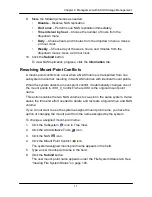
Page 130: ...oints When the system detects a mount point conflict it automatically changes one of the mount points to XXX_0_Conflict where XXX is the original mount point name This action enables the two NAS volumes to co exist in the same system It also saves the time and effort needed to delete and recreate a logical drive and NAS volume If you do not want to use the system assigned mount point name you have...

Page 131: ...View 2 Click the Administrative Tools icon 3 Click the Storage Services icon 4 Click the Initiators tab in Management View 5 From the Initiators tab dropdown menu choose Add Initiator 6 Enter the initiator s name in the Initiator Name field An iSCSI initiator name is the iSCSI name of the initiator device and is composed of a single text string Obtain the initiator name from the initiator utility ...

Page 132: ...4 Click the LUN Map tab in Management View 5 Click the LUN Masking Enabled box 6 Click the Submit button Adding a LUN Map To edit the LUN Map 1 Click the Subsystem icon in Tree View 2 Click the Administrative Tools icon 3 Click the Storage Services icon 4 Click the LUN Map tab in Management View and from the dropdown menu choose Add a LUN Map 5 Choose an initiator from the Initiator dropdown list ...

Page 133: ...he LUN Map tab in Management View 5 From the LUN Mapping Masking Information list choose an initiator and click its link Or enter the initiator s name in the Initiator Name field Note that the initiator name you input must match exactly in order for the connection to work 6 In the LUN field enter the LUNs for each logical drive You must enter different LUN numbers for each logical drive 7 Click th...

Page 134: ...ting link in Management View 4 Enter the IP address for your SMTP server 5 Enter server port number for your SMTP server 25 is the default 6 Choose Yes to enable SMTP authentication or No to disable 7 If you chose Yes for SMTP authentication enter a Username and Password in the fields provided 8 Enter an Email sender address example RAIDmaster mycompany com 9 Enter an Email subject example ASUS St...

Page 135: ... button 2 Click OK in the confirmation box Starting or Restarting Email service To start or restart the Email service click the Start or Restart button Making SLP Settings ASUS Storage s SLP service discovers services available over the Internet To make SLP service settings 1 Click the Subsystem icon in Tree View 2 Click the Administrative Tools icon Click the Automatic option to start the service...

Page 136: ...he range is 1 to 1440 minutes one day 6 If you want to use a secure connection check the Enable SSL box 7 If you checked the Enable SSL box enter a HTTPS Port number 443 is the default 8 If you want to download a SSL Certificate check the Download Certificate box 9 If you checked the Download Certificate box enter the Certificate filename or click the Browse button to locate it 10 Click the Submit...

Page 137: ...k in Management View 4 Enter the Telnet Port number 2300 is the default 5 Enter the Maximum Number of Connections 4 is the default 6 Enter the Session Time Out interval 24 minutes is the default 7 Click the Submit button 8 Click OK in the confirmation box to restart the Telnet service with your changes Changing the Startup Setting 1 Under Startup Type Click the Automatic option to start the servic...

Page 138: ...the default 5 Enter a System Name There is no default name 6 Enter a System Location USA is the default 7 Enter a System Contact the email address of the administrator or other individual 8 Enter the Read Community Public is the default 9 Enter the Write Community Private is the default To add a Trap Sink see Adding Trap Sinks below 10 Click OK in the confirmation box to restart the SNMP service w...

Page 139: ...rvice does not start during system startup 2 Click the Submit button Stopping SNMP service To stop the SNMP service 1 Click the Stop button 2 Click OK in the confirmation box Starting or Restarting SNMP service To start or restart the SNMP service click the Start or Restart button Making Netsend Settings ASUS Storage s Netsend service sends ASUS Storage subsystem events in the form of text message...

Page 140: ... Delete button to remove the recipient from the list 3 Click the Submit button 4 Click OK in the confirmation box Changing the Startup Setting 1 Under Startup Type Click the Automatic option to start the service automatically during system startup Recommended if you plan to use this feature Click the Manual option to start the service manually the service does not start during system startup The d...

Page 141: ... ASUS Storage Management If your Netsend and Messenger service settings are correct but the recipient PC does not receive event messages check the recipient PC s Firewall settings Refer to your OS documentation for more information ...

Page 142: ...the OK button The user database file is saved to the Host PC from which you access ASUS Storage Management Note The Encryption box is grayed out Encryption is always enabled Importing a User Database Caution Do NOT use this function to update the ASUS Storage firmware The Software Management Import tab enables you to import the User Database file from the Host PC s file system to the ASUS Storage ...

Page 143: ...ftware Management Import tab enables you to import a Configuration Script to the ASUS Storage DS300f or DS300i subsystem You can write a CLI configuration script to automatically configure your ASUS Storage DS300f or DS300i subsystem The script must be a plain non encrypted text file The Import function runs the script and performs the configuration automatically To import a Configuration Script t...

Page 144: ...including Component name Version number Build date Flash installation date Controller number 1 or 2 To view flash image information 1 Click the Subsystem icon in Tree View 2 Click the Administrative Tools icon The flash image information displays on the screen Running Image Info The firmware package currently running on the controllers Flashed Image Info The firmware package flashed to memory If t...

Page 145: ...ottom of the list in Management View The Restore Factory Defaults screen appears 4 Check the Firmware and Software functions you want to restore to default settings 5 Click the Submit button 6 In the confirmation box type the word confirm in the field provided 7 Click the OK button The functions you selected will be automatically restored to their default settings Clearing Statistics The Clear Sta...

Page 146: ...opdown menu On the Shutdown or Restart tab choose Poweroff from the dropdown menu 5 Click the Submit button 6 In the confirmation box type the word confirm in the field provided 7 Click the OK button When the controller shuts down your ASUS Storage Management connection will be lost 8 Wait for no less than two minutes Do one of the following actions If you chose the Shutdown Option manually turn o...

Page 147: ...ng the Shutdown To monitor a shutdown you must use the Command Line Interface CLI though a serial connection to the ASUS Storage Turn off both power supply switches when the following this message appears Shutdown complete It is now safe to power off the subsystem ...

Page 148: ...he switches off and on again On subsystems with redundant power supplies if the power switches do not respond unplug the power cords and plug them back in Try the power switches again 2 Wait about two minutes 3 Open your browser and log into ASUS Storage Management See Logging into ASUS Storage Management on page 56 If you cannot log in wait 30 seconds and try again Monitoring the Startup To monit...

Page 149: ...will appear 4 On the Shutdown or Restart tab choose Restart from the dropdown menu 5 Click the Submit button 6 In the warning box click the OK button 7 In the confirmation box type the word confirm in the field provided 8 Click the OK button When the controller shuts down your ASUS Storage Management connection will be lost 9 Wait for two to three minutes 10 In your browser log into ASUS Storage M...

Page 150: ...n in Tree View 2 Click the Controllers icon The controller information appears under the Information tab in Management View Controller information includes Controller ID 1 Alias if assigned Model if applicable Status OK means normal Viewing Controller Information To view Controller information 1 Click the Subsystem icon in Tree View 2 Click the Controllers icon 3 Click the Controller icon The cont...

Page 151: ...k the Information tab in Management View and choose Statistics from dropdown menu Clearing Statistics To clear statistics see Clearing Statistics on page 126 Making Controller Settings To make Controller settings 1 Click the Subsystem icon in Tree View 2 Click the Controllers icon 3 Click the Controller icon 4 Click the Settings tab in Management View 5 Make the following settings as needed Enter ...

Page 152: ...the controller polls all of the components in the enclosure Check the Adaptive Writeback Cache box to enable this feature Enter a power level into the HDD Power Levels field The choices are 0 Disables the feature The read write heads never park 1 Parks the read write heads after the specified period of HDD Idle Time 2 Parks the read write heads and lowers rotation speed after the specified period ...

Page 153: ...ideo applications only Reduces performance in all other applications Check the Wake on SAS box to enable this feature When enabled turns on the subsystem when there is activity on the SAS expansion Enter a temperature value in the Physical Drive Temperature Threshold field The range is 50 to 60 C 6 Click the Submit button The changes take effect immediately Clearing an Orphan Watermark An Orphan W...

Page 154: ...ery page 138 Reconditioning a Battery page 139 Making Buzzer Settings page 139 Viewing the Enclosure Information The enclosure information shown varies among different hardware versions To view information about the enclosures 1 Click the Subsystem icon in Tree View 2 Click the Enclosures icon The following information is shown Enclosure ID number Enclosure Type Operational Status Status Descripti...

Page 155: ...n which the data paths among the enclosures are connected Individual Subsystem One ASUS Storage subsystem JBOD Expansion One ASUS Storage subsystem plus one or more ASUS DS300j expansion units managed through the ASUS Storage or head unit The logical connections for these arrangements are shown the Enclosure Topology tab The physical connections for these arrangements are discussed in Chapter 2 AS...

Page 156: ...make Enclosure settings 1 Click the Subsystem icon in Tree View 2 Click the Enclosures icon 3 Click the Enclosure icon 4 Click the Settings tab in Management View 5 Enter a value in the following fields as necessary Enclosure Warning Temperature Threshold Enclosure Critical Temperature Threshold Controller Warning Temperature Threshold Controller Critical Temperature Threshold 6 Click the Submit b...

Page 157: ...he battery See Reconditioning a Battery on page 139 Reconditioning fully discharges then fully recharges the battery During reconditioning if the Adaptive Writeback Cache function is enabled the controller cache is set to Write Thru After reconditioning the cache is reset to Write Back See Making Controller Settings on page 132 If a battery reaches the threshold temperature while charging or disch...

Page 158: ...ng if the Adaptive Writeback Cache function is enabled the controller cache is set to Write Thru After reconditioning the cache is reset to Write Back See Making Controller Settings on page 132 ASUS Storage automatically reconditions the battery every two months To set the recondition schedule see Scheduling an Activity on page 72 Making Buzzer Settings To make buzzer settings 1 Click the Subsyste...

Page 159: ...orcing a Physical Drive Offline or Online page 143 Locating a Physical Drive page 144 Viewing a List of Physical Drives To view a list of physical drives in this enclosure 1 Click the Subsystem icon in Tree View 2 Click the Enclosures icon 3 Click the Enclosure icon 4 Click the Physical Drives icon The list of physical drives appears in Management View Identifying a Physical Drive To identify phys...

Page 160: ...ing From the DMA Mode dropdown menu choose a DMA mode For SAS drives check the boxes to enable Write Cache Read Look Ahead Cache Command Queuing for disk drives that support Command Queuing Read Cache 7 Click the Submit button The functions you enable here depend on whether the physical drives support those functions See Viewing Physical Drive Information on page 141 to determine which functions a...

Page 161: ...ve Settings on page 141 Viewing Physical Drive Statistics To view physical drive statistics 1 Click the Subsystem icon in Tree View 2 Click the Enclosures icon 3 Click the Enclosure icon 4 Click the Physical Drives icon 5 Click a Physical Drive icon 6 From the dropdown menu on the Information tab choose Statistics Clearing Statistics To clear statistics see Clearing Statistics on page 126 Making P...

Page 162: ... clear the condition See Physical Drive Problems on page 388 for more information To clear a Stale or PFA status from a physical drive 1 Click the Subsystem icon in Tree View 2 Click the Enclosures icon 3 Click the Enclosure icon 4 Click the Physical Drives icon 5 Click a Physical Drive icon 6 In Management View click the Clear tab 7 In the Confirmation box click OK to confirm Note If a physical d...

Page 163: ...ubsystem icon in Tree View 2 Click the Enclosures icon 3 Click the Enclosure icon 4 Click the Physical Drives icon 5 Click a Physical Drive icon 6 Click the Force Offline Online tab in Management View 7 Click the Submit button 8 In the confirmation box type the word confirm in the field provided 9 Click the OK button Locating a Physical Drive To locate a physical drive 1 Click the Subsystem icon i...

Page 164: ...14 5 Chapter 4 Management with ASUS Storage Management ...

Page 165: ...o a viable external AC power source On Battery means the external AC power source is offline and the UPS is running on battery power Model Name or Number Of the UPS unit Battery Capacity Backup capacity expressed as a percentage Loading Ratio Actual output of UPS as a percentage of the rated output See the Note below Remaining Backup Time Number of minutes the UPS is expected to power your system ...

Page 166: ...ports warnings and logs events Disable Monitors UPS only Choose an Action Mode from the dropdown menu ShutDown Shuts down the subsystem when a Threshold value is exceeded None No additional action when Threshold value is exceeded Type values into the Threshold fields See Note 2 below Running Time Remaining Threshold Actual time below this value resets adaptive writeback cache to writethrough Warni...

Page 167: ...Storage Management 2 Detection Setting must be set to Auto If a UPS is detected the setting changes to Enable 3 To specify UPS units by DNS name ask your IT administrator to add the DNS names to the DNS server before you make UPS settings ...

Page 168: ...ays appears in Management View Click the DA link to view a specific disk array See Viewing Disk Array Information on page 155 Creating a Disk Array The CLU provides three methods of creating a disk array Automatic Creates a new disk array following a default set of parameters Makes one logical drive automatically Also makes a hot spare drive for all RAID levels except RAID 0 if at least five uncon...

Page 169: ...ays icon 3 Click the Create tab in Management View 4 From the Create tab dropdown menu choose Automatic The following parameters display Disk Arrays The number of physical drives in the disk array their slot numbers configurable capacity and the number of logical drives to be created Logical Drives The ID number of the logical drive s their RAID level capacity and stripe size Spare Drives The phys...

Page 170: ... possible read write speed Mixing SATA SAS Drive Check this box if you want to use both SATA and SAS drives in the same disk array If the box is unchecked and you have both SATA and SAS drives different arrays will be created for each type of drive 6 In the Number of Logical Drives field enter the number of logical drives you want to make from this disk array 7 From the Application Type menu choos...

Page 171: ... time If you are uncertain about choosing parameters for your disk array use the Express or Automatic option to create your disk array To create a new disk array 1 Click the Subsystem icon in Tree View 2 Click the Disk Arrays icon 3 From the Create tab dropdown menu choose Advanced Step 1 Disk Array Creation 1 Enter an alias for the disk array in the field provided 2 Check the boxes to enable the ...

Page 172: ...d 3 From the RAID Level dropdown list choose a RAID level for this logical drive All RAID levels supported by the disk array appear in the list See Choosing a RAID Level on page 332 4 RAID 50 and 60 only Specify the number of axles for your array For more information on axles see RAID 30 and 50 Axles on page 329 or RAID 60 Axles on page 331 5 Enter a capacity and choose unit of measure MB GB TB Th...

Page 173: ...l drive information you specified To proceed with disk array and logical drive creation click the Submit button Note This function does not automatically create a hot spare drive After the disk array is created you can create a hot spare drive for it For more information see Creating a Spare Drive on page 172 If your logical drive was designated for NAS the File System Management Create tab appear...

Page 174: ... until synchronizing is done Critical Degraded This condition results from a physical drive failure Your data is still available However the disk array has lost redundancy fault tolerance You must determine the cause of the problem and correct it See Critical Offline Disk Arrays on page 384 Rebuilding This condition is temporary When a physical drive has been replaced the disk array automatically ...

Page 175: ...pacity of the disk array you can create additional logical drives from the same disk array To create a logical drive 1 Click the Subsystem icon in Tree View 2 Click the Disk Arrays icon 3 Click the Disk Array icon 4 Click the Create LD tab in Management View 5 iSCSI only If you plan to use this logical drive for NAS click the NAS option beside LD Type 6 Do one of the following actions For DAS and ...

Page 176: ...ices are Read Cache Read Ahead and No read Cache Read Ahead is the default See Cache Policy on page 337 From the Write Policy dropdown menu choose a Write Cache policy for this logical drive The choices are Write Through thru and Write Back Write Back is the default If you selected No Cache under Read Cache this setting will be Write Through See Cache Policy on page 337 11 Click the Update button ...

Page 177: ...in the field provided 7 Click the OK button The selected logical disappears from the Logical Drive List the Information tab Migrating a Disk Array The action of migrating a disk array means either or both Change the RAID Level Expand the storage capacity For a list of Migration options and other important information see RAID Level Migration on page 341 Notes You can add physical drives to a RAID ...

Page 178: ...he Update button The logical drive changes to reflect your choices 12 Update other logical drives using the same method 13 When you are done making the changes click the Next button 14 Click the Submit button to begin Migration To set Migration priority see Making Background Activity Settings on page 69 Rebuilding a Disk Array When you rebuild a disk array you are actually rebuilding the data on a...

Page 179: ...n the replacement target physical drive Depending the size of the physical disk involved this process will take some time To view more information click the Rebuild on PDx link To set Rebuild priority see Making Background Activity Settings on page 69 Running Media Patrol on a Disk Array Media Patrol checks the magnetic media on physical drives When it finds the specified number of bad blocks it w...

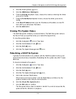
Page 180: ... HDD or SSD depending on the type of drives in the array 7 Click the Start button Transitioning a Disk Array Transition is the process of replacing a revertible spare drive that is currently part of a disk array with an unconfigured physical drive or a non revertible spare The revertible spare drive returns to its original status For more information see Transition on page 352 In order to run the ...

Page 181: ...se this feature the disk array s Operational Status must be OK When transporting a NAS logical drive from one ASUS Storage enclosure to another the firmware automatically renames the share folder to prevent a conflict To prepare a disk array for transport 1 Click the Subsystem icon in Tree View 2 Click the Disk Arrays icon 3 Click the Disk Array icon 4 Click the Transport tab in Management View 5 ...

Page 182: ...gical Drive Status OK The normal state of a logical drive For RAID Levels other than RAID 0 Striping the logical drive has full redundancy Synchronizing When you first create a logical drive the logical drive synchronizes During that time your data is available However access will be slower until synchronizing is done Rebuilding This condition is temporary When a physical drive has been replaced t...

Page 183: ...ical Drive on page 158 For a Degraded or Offline logical drive see Critical Offline Disk Arrays on page 384 Viewing Logical Drive Information To view information for a single logical drive 1 Click the Subsystem icon in Tree View 2 Click the Disk Arrays icon 3 Click the Disk Array icon 4 Click the Logical Drives icon 5 Click the Logical Drive icon To specify an Alias or set the Read and Write Polic...

Page 184: ... Click the Subsystem icon in Tree View 2 Click the Disk Arrays icon 3 Click the Disk Array icon 4 Click the Logical Drives icon 5 Click the Logical Drive icon 6 Click the Settings tab in Management View 7 Make setting changes as required Optional Enter an alias in the Logical Drive Alias field Maximum of 31 characters Use letters numbers space between words and underscore An alias is optional From...

Page 185: ... the Background Activities tab in Management View 5 From the Background Activities dropdown menu choose Initialization 6 To choose Quick Initialization check the box If you checked the box enter a value in the Quick Initialization Size field This value is the size of the initialization blocks in MB 7 If you did not choose Quick Initialization enter a hexidecimal value in the Initialization Pattern...

Page 186: ... Fix is also checked the process stops only when it finds a non repairable error 7 Click the Submit button To view the progress of the Redundancy Check click the Background Activity tab To set Redundancy Check priority see Making Background Activity Settings on page 69 Viewing the Logical Drive Check Table The Logical Drive Check Table displays errors related to a logical drive Use this informatio...

Page 187: ... Redundancy Check a background function Making Logical Drive LUN Settings LUN Masking is the process of applying a LUN Map so that each initiator can only access the LUNs specified for it Before you can specify an initiator for your LUN map you must add the initiator to the ASUS Storage s initiator list See Adding an Initiator on page 112 You must enable LUN Masking in order apply a LUN map See En...

Page 188: ...LUN However the LUN clone can be a different RAID level The choice of RAID levels depends on the disk array And if you have multiple disk arrays you can create the LUN clone on a different disk array than the original LUN You can create a LUN clone immediately using this procedure or schedule LUN cloning to run automatically at another time To create a LUN clone of a logical drive 1 Click the Subs...

Page 189: ... 10 In the confirmation box type the word confirm in the field provided and click the OK button Note the Target Logical Drive ID Use this number to identify the LUN clone in the Logical Drive list See Viewing Information for All Logical Drives on page 163 ...

Page 190: ... Drives icon The information includes ID The unique ID number assigned to the spare drive Operational Status OK is normal Can also show Rebuilding Transition Running PDM Running or Offline Physical Drive ID The ID number of the physical drive in the subsystem enclosure Capacity The data storage capacity of this spare drive Revertible Yes or No A revertible spare drive automatically returns to its ...

Page 191: ...k array Dedicated can only be used by the assigned disk arrays 5 Click the Next button 6 To make a revertible spare drive check the Revertible box A revertible spare drive can be returned to spare drive status after it replaces a failed drive in a disk array See Transition on page 352 for more information 7 To enable Media Patrol on this spare drive check the Enable Media Patrol box 8 Dedicated sp...

Page 192: ...e Subsystem icon in Tree View 2 Click the Spare Drives icon 3 Click the Delete tab in Management View 4 Check the box to the left of the spare drive you want to delete 5 Click the Submit button In the confirmation box type the word confirm in the field provided 6 Click the OK button Making Spare Drive Settings The Spare Drive Settings tab enables you to change the settings of an existing spare dri...

Page 193: ...eck Spare Check verifies the operational status of your spare drives You can also schedule a Spare Check See Scheduling an Activity on page 72 To check a spare drive 1 Click the Subsystem icon in Tree View 2 Click the Spare Drives icon 3 Click the Spare Check tab in Management View 4 From the Physical Drive dropdown menu choose the spare drive you want to check Or choose All to check all the spare...

Page 194: ...on in Tree View 2 Click the Drive Summary icon 3 Click the Logical Drive icon The information and location for the logical drive appear in Management View See Viewing Logical Drive Information page 164 Creating a LUN Clone A LUN clone is an exact copy of the original LUN or logical drive including all the data it contains at one point in time Use a LUN clone as a backup or to migrate a LUN from on...

Page 195: ...D level for the LUN clone 6 From the Copy Numbers dropdown menu to the right of the Storage Pool disk array you want to use choose the number of LUN clones you want to create You can create up to 8 clones of a LUN at a time 7 Click the Submit button 8 In the confirmation box type the word confirm in the field provided and click the OK button Note the Target Logical Drive ID Use this number to iden...

Page 196: ...a connection see page 24 Logical drives configured for NAS see page 51 If you have not installed Smart NAS Console see Installing Smart NAS Console on page 36 Also see Appendix A Setting up NAS Network Drives on page 407 Starting Smart NAS Console During installation Smart NAS Console is configured to start automatically when you boot your PC If you quit Smart NAS Console without rebooting or you ...

Page 197: ...ose Language from the popup menu 2 Highlight and click the language you want Smart NAS Console displays in the chosen language Closing Smart NAS Console Smart NAS Console is designed to be available at all times on your PC However you can close Smart NAS Console To close Smart NAS Console right click the Smart NAS Console icon in the Windows tray and choose Close from the popup menu ...

Page 198: ...ces on your network A NAS device is a logical drive with the NAS feature enabled The NAS device is listed by the unit number and IP address of the ASUS Storage subsystem For information about how to create NAS enabled logical drives See page 49 or page 156 Also see Appendix A Setting up NAS Network Drives on page 407 The Device List shows NAS devices as Blue icon bold type Currently selected Blue ...

Page 199: ...work Drives on page 407 When Smart NAS Console starts it checks the network for NAS devices Smart NAS Console automatically detects NAS when they are added to the network To add a NAS devices to the Smart NAS Console Device list 1 Under the Device List right click Click here to refresh and choose Find NAS over WWW The IP dialog box opens 2 In the IP dialog box type the IP address of the ASUS Stora...

Page 200: ...blue icon and shows an IP address To log into a NAS device 1 Right click the ASUS Storage NAS subsystem and choose Login as from the popup menu Or double click the ASUS Storage NAS subsystem The Device Login dialog box appears 2 In the Device Login dialog box enter your user name and password in the fields provided The default user name is administrator The default password is password ...

Page 201: ...ee page 102 enter your domain name and a backslash before your user name Example directory com user A Warning dialog box appears 4 In the Warning dialog box click the Yes button The ASUS Storage NAS system appears At the top left of the Smart NAS Console window In the device drop down menu ...

Page 202: ...is feature makes network settings on a ASUS Storage NAS system currently running on the network Important See your network administrator for help in making these settings To make network settings 1 Click the Setup Wizard icon at the top of the screen 2 Click the Network Setting icon at the bottom of the screen 3 Choose a setting method Automatic Enables your DHCP server to make the settings Manual...

Page 203: ... the confirmation box click the Yes button Smart NAS Console returns to the opening screen You must log into the ASUS Storage system again Deleting a NAS Device When NAS device displays a grayed out icon and its IP address says Unknown you have the option of deleting that NAS device from the Device List The action of deleting a NAS device only affects the Smart NAS Console Device List It has no ef...

Page 204: ...mmediate backup of your files from your PC to the NAS system ASUS Storage To perform an immediate backup 1 Click the SmartSYNC icon at the top of the screen 2 Click the Backup icon at the bottom of the screen 3 Under Backup your data to from the dropdown menus choose A ASUS Storage subsystem Destination folder 4 Check the Backup My Data box This action automatically selects folders on your PC incl...

Page 205: ...NC icon at the top of the window 2 Click the Backup icon at the bottom of the window 3 Under Backup your data to from the dropdown menus choose A ASUS Storage subsystem Destination folder 4 Check the Backup My Data box This action automatically selects folders on your PC including My Documents Favorites and Desktop folders with all their contents 5 To add more files Click the Add Folders Icon righ...

Page 206: ...r of hours Time of day Day of the week 9 Click the Add button to set the scheduled backup The new schedule appears in the Schedule List Monitoring Backup Progress To view the list of current backup operations 1 Click the SmartSYNC icon at the top of the window 2 Click the Progress Monitor icon at the bottom of the window The list of current backups in progress appears ...

Page 207: ...r changes to the Backup target system Files to be backed up 6 Click the Schedule button 7 As needed make your changes to the Number of hours Time of day Day of the week 8 Check the Add button The modified schedule appears in the Schedule List Running a Scheduled Backup Now To run a scheduled backup immediately 1 Click the SmartSYNC icon at the top of the window 2 Click the Schedule List icon at th...

Page 208: ... folder whose contents you want to restore 4 Click an option button for Restore to original folder The backup files will overwrite the files on your PC Restore to a specific folder No files are overwritten on your PC 5 If you chose Restore to a specific folder do one of the following actions Type the name of an existing folder in the field provided Type the name of an new folder in the field provi...

Page 209: ...n the Date Time header to reverse the chronological order To save a copy of the Backup Event Log as a text file 1 Click the SmartSYNC icon at the top of the window 2 Click the Event Log icon at the bottom of the window 3 Click the Save button 4 Optional Change the file name or save to a different location 5 Click the Save button in the Save dialog box The event log is saved on your PC right Cleari...

Page 210: ...9 and _ No spaces 4 Choose a Volume for the Share Folder from the dropdown list 5 Click the OK button 6 Click the Yes button in the confirmation box The new folder appears in the Share Folder List Opening a Share Folder This feature opens share folders in the file browser and allows you to move files to and from the share folder To open a share folder 1 Click the Share Folder icon at the top of th...

Page 211: ...Read only Read and Write 5 Click the OK button The permission change happens immediately Changing the Host IP address To change the host IP address 1 Click the Share Folder icon at the top of the window 2 Click the Setting icon at the bottom of the window 3 From the Host IP dropdown menu choose the Host IP you want to use 4 Click the OK button The permission change happens immediately Deleting a S...

Page 212: ...k drive 4 Choose a device name drive letter from the dropdown menu 5 Click the Mount button The share folder appears on your PC as a mounted or network drive Un mounting a Share Folder Disconnecting a Network Drive To un mount a share folder Linux or disconnect a network drive Windows 1 Click the Share Folder icon at the top of the window 2 Click the Mount Share Folder icon at the bottom of the wi...

Page 213: ... Click the Create New User icon at the bottom of the screen 3 Type a Username in the field provided Up to 16 characters A Z 0 9 and _ first character must be a letter No spaces 4 Type a Password in the field provided Up to 16 characters A Z and 0 9 No spaces 5 Retype the Password in the Confirm field 6 Click the OK button 7 In the confirmation box click the Yes button Note These users can access t...

Page 214: ...n 3 Click the share folder whose permissions you want to change 4 For each user in the list click one of the following options Deny access Read only Read and Write 5 Click the OK button The permission change happens immediately Viewing a List of Users To view a list of Users 1 Click the User Management icon at the top of the screen 2 Click the User List icon The User List appears You might have to...

Page 215: ...of Groups 1 Click the User Management icon at the top of the screen 2 Click the Group List icon at the bottom of the screen Adding Members to a Group Note A User can only belong to one Group If a User already belongs to a Group and you add him to this Group you automatically delete him from the previous Group To add Users as Group members 1 Click the User Management icon at the top of the screen 2...

Page 216: ...to change 4 Click a user in the Selected User list then click the arrow icon to move them to the Available User list 5 Click the OK button Deleting a Group Before you can delete a Group you must first delete all of the Members from the Group See Deleting Members from a Group on page 197 To delete a Group 1 Click the User Management icon at the top of the screen 2 Click the Delete Group icon at the...

Page 217: ...t the subsystem 1 Click the NAS Management icon at the top of the screen The Shutdown icon at the bottom of the screen is automatically selected 2 Click the Restart option button 3 Click the OK button When the controller restarts your Smart NAS Console connection is interrupted 4 Monitor the subsystem in the Device List When the subsystem icon changes from gray to blue click the subsystem to displ...

Page 218: ...wo minutes 5 Unplug the power cord or cords then plug them back in to activate the power switches Caution After you power off the subsystem wait at least 10 seconds before you power on the subsystem again Monitoring the Power Off To monitor a power off you must use the Command Line Interface CLI though a serial connection to the ASUS Storage Turn off both power supply switches when the following t...

Page 219: ...off the power supply switch both switches with redundant power supplies on the back of the subsystem Caution After you power off the subsystem wait at least 10 seconds before you power on the subsystem again Monitoring the Shutdown To monitor a shutdown you must use the Command Line Interface CLI though a serial connection to the ASUS Storage Turn off both power supply switches when the following ...

Page 220: ...subsystem To create a RAID volume see Creating a Disk Array Advanced on page 152 and Creating a Logical Drive on page 156 Viewing a List of RAID Volumes To view a list of RAID Volumes 1 Click the Volume Configuration icon at the top of the screen 2 Click the Volume List icon at the bottom of the screen 3 Click the RAID Volume in the list whose information you want to view RAID Volume information i...

Page 221: ...202 Chapter 5 SmartNAVI ...

Page 222: ... 246 Managing iSCSI Connections page 250 Managing Background Activity page 257 Working with the Event Viewer page 259 Working with LUN Mapping page 261 Managing UPS Units page 263 Managing Users page 266 Working with Software Management page 269 Flashing through TFTP page 275 Viewing Flash Image Information page 275 Clearing Statistics page 275 Restoring Factory Defaults page 276 Shutting Down the...

Page 223: ...207 Making a Serial Connection Before you begin be sure the RJ11 to DB9 serial data cable is connected between the Host PC and ASUS Storage subsystem and that both machines are booted and running Figure 1 Serial port on the controller Serial port Then do the following actions 1 Change your terminal emulation program settings to match the following specifications Bits per second 115200 Data bits 8 ...

Page 224: ...minal icon Linux 2 Type telnet 192 168 1 56 2300 and press Enter The IP address above is only an example Use your ASUS Storage s Management port IP address 2300 is the Telnet port for the ASUS Storage 3 Press Enter once to launch the CLI Logging In 1 At the Login prompt type the user name and press Enter The default user name is administrator 2 At the Password prompt type the password and press En...

Page 225: ...ray Management View disk array information create and delete disk arrays transport rebuild PDM and transition functions and locate a disk array create and delete logical drives Spare Drive Management View a list of spare drives create modify and delete spare drives and run spare check Logical Drive Management View logical drive information name logical drives initialization and redundancy check an...

Page 226: ...lp on any CLU screen press Ctrl E To return to the CLU press Enter Exiting the CLU 1 Highlight Return to Previous Menu and press Enter Repeat this action until you arrive at the Main Menu 2 From the Main Menu highlight Return to CLI and press Enter to exit 3 Close the terminal emulation Telnet or terminal window Logging Out of the CLI When you shut down or restart the ASUS Storage subsystem you ar...

Page 227: ...208 Chapter 6 Management with the CLU Running Quick Setup Quick Setup is discussed under Setting up with the CLU on page 43 ...

Page 228: ... to save your settings Running Media Patrol Media Patrol is a routine maintenance procedure that checks the magnetic media on each disk drive Media Patrol checks all physical drives assigned to disk arrays and spare drives It does not check unconfigured drives To start stop pause or resume Media Patrol 1 From the Main Menu highlight Subsystem Management and press Enter 2 Highlight Media Patrol and...

Page 229: ...and press Enter 2 Highlight Lock Management and press Enter 3 Highlight Unlock and press Enter Releasing a Lock set by another user To release somebody else s lock 1 From the Main Menu highlight Subsystem Management and press Enter 2 Highlight Lock Management and press Enter 3 Highlight Force Unlock and press the Spacebar to change to Yes 4 Highlight Unlock and press Enter Setting Subsystem Date a...

Page 230: ...s the ASUS Storage subsystem synchronizes At startup Every night When you synchronize manually To set a Network Time Protocol NTP for this subsystem 1 From the Main Menu highlight Subsystem Management and press Enter 2 Highlight NTP Management and press Enter 3 Highlight NTP Settings and press Enter 4 Highlight NTP Service and press the spacebar to toggle to Enable 5 Highlight Time Servers and inp...

Page 231: ...r settings 10 Press Y to confirm Synchronizing the Subsystem NTP Manually The NTP service must be enabled before you can manually synchronize the subsystem See Setting Subsystem NTP on page 211 To synchronize the ASUS Storage subsystem with an NTP Server 1 From the Main Menu highlight Subsystem Management and press Enter 2 Highlight NTP Management and press Enter 3 Highlight Start Time Sync and pr...

Page 232: ...rmation and press Enter To access controller statistics highlight Controller Statistics and press Enter Clearing an Orphan Watermark This condition is the result of a disk drive failure during an NVRAM RAID level migration on a disk array To clear an orphan watermark 1 From the Main Menu highlight Subsystem Management and press Enter 2 Highlight Controller Management and press Enter 3 Highlight on...

Page 233: ...aptive Writeback Cache and press the spacebar to toggle between Enabled and Disabled Highlight Forced Read Ahead cache and press the spacebar to toggle between Enabled and Disabled Highlight Cache Flush Interval and press the backspace key to erase the current value Type a new interval value 1 to 12 seconds Highlight Physical Drive Temperature Threshold and press the backspace key to erase the cur...

Page 234: ...ble Highlight HDD Standby Time and press the backspace key to erase the current value Type a new interval value 1 to 1440 minutes or 0 to disable Highlight HDD Stopped Time and press the backspace key to erase the current value Type a new interval value 10 to 1440 minutes or 0 to disable Highlight Wake on SAS and press the spacebar to toggle between Enable and Disable Highlight Rescue Mode and pre...

Page 235: ...216 Chapter 6 Management with the CLU Figure 4 Controller Status LED Controller Status ...

Page 236: ...ion status settings and location To access Enclosure Management 1 From the Main Menu highlight Subsystem Management and press Enter 2 Highlight Enclosure Management and press Enter To access FPU VPD information vital product data on field replaceable units highlight FPU VPD Information and press Enter This function lists the battery backup unit and backplane Viewing Power Supply Status To view the...

Page 237: ...hold there is a fan malfunction See Replacing a Cooling Fan on page 313 Viewing Voltage Sensor Status To view the status of the voltage sensors 1 From the Main Menu highlight Subsystem Management and press Enter 2 Highlight Enclosure Management and press Enter 3 Highlight Voltage Sensors and press Enter If any voltage is outside the Healthy Threshold values there is a voltage malfunction in the en...

Page 238: ...onding controller is not present the battery will not appear in the interface If a battery does not reflect normal conditions and it is not currently under reconditioning run the Recondition function before you replace the battery See Reconditioning a Battery on page 220 Reconditioning fully discharges then fully recharges the battery During reconditioning if the Adaptive Writeback Cache function ...

Page 239: ... Reconditioning fully discharges then fully recharges the battery During reconditioning if the Adaptive Writeback Cache function is enabled the controller cache is set to Write Thru After reconditioning the cache is reset to Write Back See Making Controller Settings on page 213 Locating an Enclosure This feature helps you identify the physical ASUS Storage enclosure you are working with through th...

Page 240: ...s are connected Individual Subsystem One ASUS Storage subsystem JBOD Expansion One ASUS Storage subsystem plus one or more ASUS DS300j expansion units managed through the ASUS Storage or head unit The physical connections for these arrangements are discussed in Chapter 2 ASUS Storage Installation on page 9 To view enclosure topology 1 From the Main Menu highlight Subsystem Management and press Ent...

Page 241: ...ter 2 Highlight Global Physical Drives Settings and press Enter 3 Change the following settings as required For SATA drives Highlight Write Cache and press the spacebar to toggle between Enabled and Disabled Highlight Read Look Ahead Cache and press the spacebar to toggle between Enabled and Disabled Highlight CmdQueuing and press the spacebar to toggle between Enabled and Disabled Highlight DMA M...

Page 242: ... Drive Management and press Enter 2 Highlight the physical drive of your choice and press Enter 3 Highlight Physical Drive Statistics and press Enter Clearing Stale and PFA Conditions The Clear Stale and Clear PFA functions only appear when those conditions exist on the physical drive To clear a Stale or PFA condition on a physical drive 1 From the Main Menu highlight Physical Drive Management and...

Page 243: ...hysical drive offline or online 1 From the Main Menu highlight Physical Drive Management and press Enter 2 Highlight Global Physical Drives Settings and press Enter 3 Highlight the physical drive of your choice and press Enter 4 Highlight Force Offline or Force Online and press Enter 5 Press Y to confirm Locating a Physical Drive This feature helps you identify a physical drive within the ASUS Sto...

Page 244: ...efault set of parameters Makes one logical drive automatically Also makes a hot spare drive for all RAID levels except RAID 0 if at least five unconfigured physical drives are available If you have multiple enclosures multiple disk array and logical drive sets are created See Creating a Disk Array Automatic on page 226 Express You choose the parameters for a new disk array by specifying the charac...

Page 245: ...nfiguration and create the disk array and logical drive s highlight Save Configuration and press Enter To reject the proposed configuration highlight Cancel Array Configuration and press Enter You will return to the Disk Arrays Summary screen To create a disk array with different characteristics repeat the steps above specifying different parameters but choose the Express or Advanced option If you...

Page 246: ... the applications and choose the best one for your disk array File Server Video Stream Transaction Data Transaction Log Other 8 Press Ctrl A to save your settings and move to the next screen 9 Review the proposed configuration of disk array and logical drive s To accept the proposed configuration and create the disk array and logical drive s highlight Save Configuration and press Enter To reject t...

Page 247: ...Ds and SSDs in the same disk array 8 Highlight Save Settings and Continue and press Enter 9 If you want to specify an alias to the logical drive highlight Alias and type a name Maximum of 31 characters Use letters numbers space between words and underscore 10 Highlight RAID Level and press the spacebar to toggle though a list of available RAID levels 11 If you want to create multiple logical drive...

Page 248: ...ith the logical drive s highlight Return to Previous Screen and press Enter to begin the process again Deleting a Disk Array Caution When you delete a disk array you delete all the logical drives and the data they contain Back up all important data before deleting a disk array 1 From the Main Menu highlight Disk Array Management and press Enter 2 Highlight the disk array you want to delete and pre...

Page 249: ...Transport Ready The result of a successful Prepare for Transport operation You remove the physical drives of this disk array and move them to another enclosure or to different drive slots in the same enclosure After you relocate the physical drives the disk array status will show OK Setting an Alias for a Disk Array This function sets an alias for the disk array To set an alias 1 From the Main Men...

Page 250: ...nt and press Enter 3 Highlight PDM and press the spacebar to toggle between Enable and Disable 4 Press Ctrl A to save your settings See Running PDM on page 233 Preparing the Disk Array for Transport To run the Transport function on a disk array 1 From the Main Menu highlight Disk Array Management and press Enter 2 Highlight the disk array you want and press Enter 3 Highlight Transport and press En...

Page 251: ...u can add physical drives to a RAID 50 or 60 array but you cannot change the number of axles If you add an odd number of physical drives to a RAID 10 array it will become a RAID 1E array by default 6 Highlight Save Settings and Continue and press Enter 7 To change RAID level Highlight the logical drive in the list and press Enter 8 Highlight RAID Level and press the spacebar to toggle through the ...

Page 252: ...drive that is currently part of a disk array with an unconfigured physical drive or a non revertible spare drive For more information see Transition on page 352 In order to run Transition The spare drive must be Revertible You must have an unconfigured physical drive of the same or larger capacity and the same type HDD or SSD to replace the spare drive To run Transition on a disk array 1 From the ...

Page 253: ... Management and press Enter 2 Highlight the disk array in which you want to create a logical drive and press Enter 3 Highlight Create New Logical Drive and press Enter The Disk Array ID number and Maximum capacity available for the new logical drive are displayed 4 Highlight the following parameters and press the backspace key to erase the current value Alias Type an alias into the field if desire...

Page 254: ...t Deleting a Logical Drive Caution When you delete a logical drive you delete all the data it contains Back up all important data before deleting a logical drive To delete a logical drive from a disk array 1 From the Main Menu highlight Disk Array Management and press Enter 2 Highlight the disk array that contains the logical drive you want to delete and press Enter 3 Highlight the logical drive y...

Page 255: ...ore information Type Global all disk arrays or Dedicated to specified disk arrays Dedicated to Array The array to which a dedicated spare is assigned Creating a Spare Drive Only unconfigured physical drives can be used to make spares Check your available drives under Physical Drive Management See Managing Physical Drives on page 222 1 From the Main Menu highlight Spare Drive Management and press E...

Page 256: ...and press Enter A list of the current spare drives appears including the following parameters 2 Highlight the spare drive you want to change and press Enter 3 Highlight the setting you want to change Revertible A revertible drive can be returned to spare status after you replace the failed drive in a disk array See Transition on page 352 for more information Type Dedicated means this spare drive c...

Page 257: ...vide a new spare drive To delete a spare drive 1 From the Main Menu highlight Spare Drive Management and press Enter A list of the current spare drives appears 2 Highlight the spare drive you want to delete and press the spacebar to mark it The mark is an asterisk to the left of the listing 3 Highlight Delete Marked Spare Drives and press Enter 4 Press Y to confirm the deletion ...

Page 258: ... and settings screen appears 3 Highlight any of the following and press Enter to view more information Check Table Read Check Write Check and Inconsistency Check Tables Logical Drive Statistics Making Logical Drive Settings 1 From the Main Menu highlight Logical Drive Management and press Enter 2 Highlight the logical drive you want and press Enter 3 For the following items accept the existing set...

Page 259: ...ick Initialization Size Enter a value for the first and last sections of the logical drive to be initialized or use the default 64 MB To change a parameter highlight it and press the backspace key to erase the current value then type the new value 5 Highlight Start and press Enter If necessary you can pause and resume or stop and restart the Initialization You cannot access the logical drive until...

Page 260: ...cy Check is running Locating a Logical Drive This feature helps you identify the physical drives assigned to the logical drive you are working with in the CLU To locate a logical drive 1 From the Main Menu highlight Logical Drive Management and press Enter 2 Highlight the disk array you want and press Enter 3 Highlight Locate Logical Drive and press Enter The disk status LEDs for the physical driv...

Page 261: ...f a logical drive 1 From the Main Menu highlight Logical Drive Management and press Enter 2 Highlight the logical drive you want to clone and press Enter 3 Highlight LUN Clone and press Enter 4 Highlight RAID Level of Copies and press the space bar to toggle through the available RAID levels until the RAID level you want is shown 5 Highlight Save Settings and Continue and press Enter 6 Highlight t...

Page 262: ... highlight Network Management and press Enter 2 Highlight the management port and press Enter 3 Highlight NetMgmt Ethernet Port Settings and press Enter 4 Highlight DHCP and press the spacebar to toggle to Enable 5 Highlight TCP Port Number to change the entry 3260 is the default and recommended for most applications 6 Press Ctrl A to save your settings Making Manual Settings 1 From the Main Menu ...

Page 263: ...er to change the entry 3260 is the default and recommended for most applications 6 Press Ctrl A to save your settings Making Manual Settings 1 From the Main Menu highlight Network Management and press Enter 2 Highlight the management port and press Enter 3 Highlight NetMgmt Ethernet Port Settings and press Enter 4 Highlight DHCP and press the spacebar to toggle to Disable 5 Highlight each of the f...

Page 264: ...ighlight Link Aggregation and press Enter The list of Link Aggregation entries appears Changing a Link Aggregation Entry 1 From the Main Menu highlight Network Management and press Enter 2 Highlight Link Aggregation and press Enter 3 Highlight a Link Aggregation entry in the list and press Enter 4 Highlight Master Port and press the spacebar to toggle to one of the iSCSI port numbers 5 Highlight S...

Page 265: ...s Enter 2 Highlight Fibre Channel Node and press Enter Node information appears There are no user settings on this screen Viewing Fibre Channel Logged in Devices To view a list of logged in devices 1 From the Main Menu highlight Fibre Channel Management and press Enter 2 Highlight Fibre Channel Ports and press Enter 3 Highlight the port you want and press Enter 4 Highlight Logged In Devices and pr...

Page 266: ...ct Point to Point Private Loop Example 1 If you connect the ASUS Storage to a Fibre Channel switch and choose NL Port topology you will create a Fabric Direct attached topology Example 2 If you have a Point to Point attached topology you made a direct connection no switch and chose N port topology Note In some cases HBA settings to N Port only work if connected to the switch Refer to your HBA manu...

Page 267: ...ince last reset LIPCount Loop Initialization Primitive Sequence This primitive sequence applies only to the arbitrated loop topology It is transmitted by an L_Port to initialize or re initialize the loop NOSCount Not Operational Primitive Sequence This primitive sequence is used during link initialization between two N_Ports in the point to point topology or an N_Port and an F_Port in the fabric t...

Page 268: ...itiators LUN Mapping must be enabled in order for ASUS Storage to recognize a Fibre Channel See Enabling LUN Mapping on page 261 To view Fibre Channel initiators 1 From the Main Menu highlight Fibre Channel Management and press Enter 2 Highlight Fibre Channel Initiators and press Enter A list of all currently logged in initiators appears on the screen Adding a Fibre Channel Initiator LUN Mapping m...

Page 269: ...is document For more information contact the Internet Engineering Task Force at http www ietf org Viewing iSCSI Node Information There are four iSCSI data ports on the controller To view information about the iSCSI ports 1 From the Main Menu highlight iSCSI Management and press Enter 2 Highlight iSCSI Node and press Enter The node information appears on the screen Making iSCSI Node Settings The iS...

Page 270: ...est CRC See note below Data Digest Enables use of a Data Digest CRC See note below Uni directional CHAP Authentication Enables Challenge Handshake Authentication Protocol Bi directional CHAP Authentication 6 Press Ctrl A to save your settings Notes Header Digest and Data Digest work best with initiators equipped with a TCP Offload Engine TOE Refer to your iSCSI HBA user manual for more information...

Page 271: ...rt settings 1 From the Main Menu highlight iSCSI Management and press Enter 2 Highlight iSCSI Ports and press Enter 3 Highlight Target Port 1 Target Port 2 Target Port 3 or Target Port 4 and press Enter 4 Highlight MAC Layer Statistics IP Layer Statistics or TCP Layer Statistics and press Enter The screen displays statistics for the layer you chose Viewing the iSCSI Portal An iSCSI Portal is an iS...

Page 272: ... ports Internet Storage Name Service iSNS is a protocol used to facilitate the automated discovery management and configuration of iSCSI devices on a TCP IP network View Settings To view iSNS settings 1 From the Main Menu highlight iSCSI Management and press Enter 2 Highlight iSCSI iSNS Options and press Enter The screen displays the following information iSNS status Enabled or disabled ESI status...

Page 273: ...g of a sequence number and a random number Both the sender and peer share a predefined secret or password The peer concatenates the sequence number the random value and the secret and calculates a hash using a one way hash algorithm such as MD5 The peer sends the hash value back to the authenticator which in turn builds that same string on its side calculates the hash and compares the result with ...

Page 274: ...is bi directional authentication 6 Highlight Secret and type a word of 12 to 16 characters 7 Highlight Retype Secret and type the same word again 8 Press Ctrl A to save your settings Editing CHAPs To Edit a CHAP 1 From the Main Menu highlight iSCSI Management and press Enter 2 Highlight iSCSI CHAPs and press Enter 3 Highlight the CHAP in the list and press Enter 4 Do one or both of the following a...

Page 275: ...can send a ping through ASUS Storage s iSCSI data ports to verify a network connection To send a ping 1 From the Main Menu highlight iSCSI Management and press Enter 2 Highlight Ping and press Enter 3 Highlight IP Address and type the IP address you want to ping 4 Highlight Ping Through and press the spacebar to toggle though port numbers to choose an iSCSI data port 5 Highlight Ping and press Ent...

Page 276: ...e Main Menu highlight Background Activity and press Enter A count of current background activities appears including Rebuild PDM Predictive Data Migration Synchronization Redundancy Check Migration Transition Initialization Media Patrol Making Background Activity Settings 1 From the Main Menu highlight Background Activity and press Enter 2 Highlight Background Activity Settings and press Enter 3 H...

Page 277: ...tegrity on disk arrays Initialization Sets all data bits in the logical drive to zero Redundancy Check Checks reports and can correct data inconsistencies in logical drives The rates are defined as follows Low Fewer resources to activity more to data read write Medium Balance of resources to activity and data read write High More resources to activity fewer to data read write 5 Highlight the follo...

Page 278: ...ations of the condition are serious Fatal Non Recoverable error or failure has occurred None Deactivates this event for notification purposes Viewing Runtime Events Runtime events refer to the 1023 most recent events recorded since the subsystem was started Runtime events are lost when the subsystem shuts down To display Runtime Events 1 From the Main Menu highlight Event Viewer and press Enter Th...

Page 279: ...2 Highlight NVRAM Events and press Enter The log of NVRAM Events appears Events are added to the top of the list Each item includes Sequence number Begins with 0 at system startup Device Disk Array Logical Drive Physical Drive by its ID number Severity See the list on page 259 Timestamp Date and time the event happened Description A description of the event in plain language 3 Press the up and dow...

Page 280: ... A list of the current initiators appears Enabling LUN Mapping To enable LUN mapping 1 From the Main Menu highlight Additional Info and Management and press Enter 2 Highlight LUN Mapping and press Enter A list of the current iSCSI initiators appears LUN Mapping must be enabled in order for ASUS Storage to recognize the initiator If LUN Mapping is currently disabled highlight Enable LUN Mapping and...

Page 281: ... To map a LUN to an initiator 1 From the Main Menu highlight Additional Info and Management and press Enter 2 Highlight LUN Mapping and press Enter 3 Highlight an existing Initiator and press Enter A list of logical drives displays 4 In the LUN field press the backspace key to erase the current value then type the LUN you want to assign to this initiator from 0 to 255 If you make a error press Ctr...

Page 282: ...AC means the UPS is connected to a viable external AC power source On Battery means the external AC power source is offline and the UPS is running on battery power Model Name or Number Capacity Backup capacity expressed as a percentage Loading Actual output of UPS as a percentage of the rated output See the Note below Remaining Minutes Number of minutes the UPS is expected to power your system in ...

Page 283: ...rs UPS Settings changes reports warnings and logs events Disable Monitors UPS only Choose an Action Mode from the dropdown menu Shutdown Shuts down the subsystem when a Threshold value is exceeded None No additional action when Threshold value is exceeded Type values into the Threshold fields See Note 2 below Running Time Remaining Threshold Actual time below this value resets adaptive writeback c...

Page 284: ... want and press Enter UPS information includes Voltage Rating Output voltage of the UPS Battery Capacity Backup capacity expressed as a percentage Remaining Backup Time Number of minutes the UPS is expected to power your system in the event of a power failure Loading Ratio Actual output of UPS as a percentage of the rated output See the Note below Note The maximum recommended Loading Ratio varies ...

Page 285: ...st of the current users appears Creating a User To create a new user account 1 From the Main Menu highlight Additional Info and Management and press Enter 2 Highlight User Management and press Enter 3 Highlight Create New User and press Enter 4 Highlight each field and type in the appropriate information User name no spaces Password Optional Maximum 31 characters Use letters numbers and underscore...

Page 286: ... can change other user s passwords To change a user s password 1 From the Main Menu highlight Additional Info and Management and press Enter 2 Highlight User Management and press Enter 3 Highlight a User in the list and press Enter 4 Highlight Change Password and press Enter 5 Highlight New Password and type a password Maximum 31 characters Use letters numbers and underscore 6 Highlight Retype Pas...

Page 287: ...e options For definitions of each privilege level see List of User Privileges on page 267 7 Highlight Status and press the space bar to toggle between the options Enabled Allows the user to log in to the system Disabled Prevents the user from logging in to the system 8 Press Ctrl A to save the settings Deleting a User To delete a user 1 Log in under a user name other than the one you want to delet...

Page 288: ...light Software Management and press Enter 3 Highlight Email and press Enter 4 Highlight Startup Type and press the spacebar to toggle between Automatic and Manual 5 Highlight the following and press the backspace key to erase the current value then type the new value Server IP address Server Port number 25 is the default 6 Highlight Authentication and press the spacebar to toggle between Yes and N...

Page 289: ...us is Started To make Web Server service settings 1 From the Main Menu highlight Additional Info and Management and press Enter 2 Highlight Software Management and press Enter 3 Highlight Web Server and press Enter 4 Highlight Startup Type and press the spacebar to toggle between Automatic and Manual 5 Highlight the following and press the backspace key to erase the current value then type the new...

Page 290: ...tart stop or restart the Telnet service highlight Start Stop or Restart and press Enter Making SNMP Settings By default SNMP Simple Network Management Protocol service is set to Automatic and its normal status is Started To make SNMP service settings 1 From the Main Menu highlight Additional Info and Management and press Enter 2 Highlight Software Management and press Enter 3 Highlight SNMP and pr...

Page 291: ...r 2 Highlight Software Management and press Enter 3 Highlight Create New Trap Sink and press Enter 4 Highlight Trap Sink IP address and press the backspace key to erase the current value then type the new IP address in this field 5 Highlight Trap Filter and press the spacebar to toggle through the severity levels The Severity Levels are lowest to highest Information Warning Minor Major Critical an...

Page 292: ...he recipient PC in order to receive reports Adding a recipient To add a recipient 1 From the Main Menu highlight Additional Info and Management and press Enter 2 Highlight Software Management and press Enter 1 Highlight Netsend and press Enter 2 Highlight Message Recipient and press Enter 3 Highlight Create New Message Recipient and press Enter 4 Type the recipient s IP address into the field prov...

Page 293: ...nt and press Enter 2 Highlight Software Management and press Enter 3 Highlight the recipient you want to delete and press the spacebar to mark it The mark is an asterisk to the left of the listing 4 Highlight Delete Marked Entries and press Enter Netsend Requirements In order to use Netsend NetSend must be running the ASUS Storage You must provide the IP address for each recipient PC The Messenger...

Page 294: ...The firmware package currently running on the controllers Flashed Image Info The firmware package flashed to memory If the Running and Flashed Images do not match the ASUS Storage has not restarted since the firmware was last updated Restart the ASUS Storage to run the Flashed firmware package See Restarting the Subsystem on page 280 Note that all of these components are upgraded together in a pac...

Page 295: ...m unless you are sure this action is needed To restore factory default settings 1 From the Main Menu highlight Additional Info and Management and press Enter 2 Highlight Restore Factory Defaults and press Enter 3 Highlight the setting group you want and press the spacebar to toggle between Yes and No Yes means this setting will be restored to the default value 4 Highlight Restore Factory Defaults ...

Page 296: ...ditional Info and Management and press Enter 2 Highlight Shutdown or Restart and press Enter 3 Do one of the following actions Highlight Option and press the spacebar to display Shutdown Highlight Option and press the spacebar to display Poweroff 4 Highlight Submit and press Enter A warning message appears 5 Press Y to continue The screen goes blank 6 Wait for no less than two minutes 7 Do one of ...

Page 297: ...ress the spacebar to display Poweroff 4 Highlight Submit and press Enter A warning message appears 5 Press Y to continue 6 When you see the following message Shutdown complete It is now safe to power off the subsystem Do one of the following actions If you chose the Shutdown Option manually turn off the power supply switch both switches with redundant power supplies on the back of the subsystem If...

Page 298: ...e power cords and plug them back in Try the power switches again 2 Wait about two minutes 3 Establish a Telnet connection to the ASUS Storage See Making a Telnet Connection on page 205 If you cannot log in wait 30 seconds and try again 4 Type menu and press Enter to open the CLU Starting up the ASUS Storage Serial Connection To start the RAID subsystem 1 Manually turn on the power supply switches ...

Page 299: ...ht Additional Info and Management and press Enter 2 Highlight Shutdown or Restart and press Enter 3 Highlight Option and press the spacebar to display Restart 4 Highlight Submit and press Enter A warning message appears 5 Press Y to continue The screen goes blank 6 Wait for no less than two minutes 7 Re establish your Telnet connection to the ASUS Storage CLU If you cannot re establish a connectio...

Page 300: ...Management with the CLU 4 Highlight Submit and press Enter A warning message appears 5 Press Y to continue The screen will display shutdown and startup functions 6 When the Login prompt appears log into the CLU again ...

Page 301: ...e buzzer settings 1 From the Main Menu highlight Buzzer and press Enter A list of Controllers appears with the current buzzer setting and status 2 Highlight the Controller whose buzzer you want to set and press Enter 3 Highlight Enabled and press the spacebar to toggle between Yes and No 4 Press Ctrl A to save your settings The buzzer provides the audible alarm See ASUS Storage is Beeping on page ...

Page 302: ...LCD panel is optional and typically installed during ASUS Storage installation See page 10 The LCD panel activates approximately 35 seconds after you switch on the ASUS Storage s power supply At first the LCD screen displays System is Initializing When the ASUS Storage is fully booted and running under normal conditions the LCD screen displays the ASUS Storage model number and IP address as shown ...

Page 303: ...ernative mode setting on the bottom 5 Press the button choose the alternative mode setting The alternative LCD mode is set Simple Mode Simple Mode enables you to perform the following enclosure and RAID management functions View Events View critical events if any have been set View Controller View IP address MAC address LCD UI version Vendor name WWN memory size and firmware version Spare Drive Ma...

Page 304: ... from a physical drive Creating a revertible spare drive or a dedicated spare drive Running background activity such as Media Patrol PDM Rebuild or RAID level migration Making FC iSCSI or SAS settings Viewing event logs Shutting down or restarting the ASUS Storage Refer to Chapter 4 Management with ASUS Storage Management on page 55 and Chapter 6 Management with the CLU on page 203 when you need t...

Page 305: ...ts 1 Press the or button until the display says View Events 2 Press the button and the display the first critical event Press the button to display more information about the event Press the or button to scroll through any additional events ...

Page 306: ...e left and the button move right To set an IP address with double or single digit octets for example 192 168 1 50 type zeros as placeholders 192 168 001 050 After you have set the last extreme right digit press the button The current Subnet Mask displays with the cursor under the first extreme left digit 6 Make the needed changes the same as in step 5 After you have set the last extreme right digi...

Page 307: ...s Down reconnect to the network before preceding 3 Press the or button and the display says DHCP Disable 4 Press the button to make a change 5 Press the button to Enable 6 Press the button to confirm The display shows the new IP address set by the DHCP server ...

Page 308: ...r Information To view information about the controller 1 Press the or button until the display says View Controller 2 Press the button and the display says Vendor 3 Press the or button to scroll through the list of items Vendor Name WWN World Wide Name Memory Size Firmware Version IP Address MAC Address LCD UI Version To change memory size or update the firmware see Chapter 8 Maintenance on page 3...

Page 309: ...e Management or page 217 CLU Viewing the Enclosure This function requires the LCD to be in Advanced mode See page 284 To view enclosure information 1 Press the or button until the display says View Enclosure 2 Press the button and the display says Enclosure Status 3 Press the button again and the display says Temperature Status This is the item list It includes Temperature status Fan status Power ...

Page 310: ...r 3 Press the or button to scroll through the list of physical drives 4 Press the button choose a physical drive 5 Press the or button to scroll through the list of items Model Interface SAS or SATA Capacity Location Enclosure number and slot number Configuration Array number and sequence number or Spare Firmware version Status Locating a Physical Drive This function requires the LCD to be in Adva...

Page 311: ...292 Managing Physical Drives 6 Press the button The disk status LED for the physical drive blinks for one minute See Figure 2 Figure 2 Disk Status LED Disk Status ...

Page 312: ...matic Creation option enables you to create a new disk array following a default set of parameters One logical drive will be made automatically when you create the disk array If you have multiple enclosures a separate disk array and logical drive set will be created for each enclosure If you have both Hard Disk Drives HDD and Solid State Drives SSD separate disk array and logical drive sets will b...

Page 313: ...ess the or button until the display says Advanced Configure 4 Press the button and the display says Disk Array Create 5 Press the button again and the display says Physical Drive Select 6 Press the button again to display the available physical drives by number 7 Press the button to move through the list Press the button to choose a physical drive for your array Note that you cannot mix HDDs and S...

Page 314: ...hoices are 512 B 1 KB 2 KB and 4 KB 10 Press the or button until the display shows the sector size you want The display shows the default read policy The choices are ReadCache ReadAhead and None 11 Press the or button until the display shows the read policy you want 12 Press the button to choose the read policy shown on the screen The display shows the default write policy The choices are WriteBac...

Page 315: ...ay To delete a disk array 1 Press the or button until the display says Array Configure 2 Press the button and the display says Auto Configure 3 Press the or button until the display says Advanced Configure 4 Press the or button until the display says Disk Array Delete 5 Press the button again to display a list of disk arrays 6 Press the or button choose a disk array for deletion 7 Press the button...

Page 316: ...e However the disk array has lost redundancy fault tolerance You must determine the cause of the problem and correct it See Critical Offline Disk Arrays on page 384 Rebuilding This condition is temporary When a physical drive has been replaced the disk array automatically begins rebuilding in order to restore redundancy fault tolerance Your data is still available However access will be slower unt...

Page 317: ...e 4 Press the or button until the display says Logical Disk Create 5 Press the button again and the display says 000 6 Press the button again and the display says RAID Level 7 Press the or button until the display shows the RAID level you want Note that the available RAID levels depend on the number of physical drives in your disk array 8 Press the button to choose the RAID level shown on the scre...

Page 318: ...ed the LCD returns to Logical Disk Create Deleting a Logical Drive Caution When you delete a logical drive you delete all the data it contains Back up all important data before deleting a logical drive To delete a logical drive from a disk array 1 Press the or button until the display says Array Configure 2 Press the button and the display says Auto Configure 3 Press the or button until the displa...

Page 319: ... data is available However access will be slower until synchronizing is done Rebuilding This condition is temporary When a physical drive has been replaced the logical drive automatically begins rebuilding in order to restore redundancy fault tolerance Your data is still available However access will be slower until rebuilding is done Critical This condition results from a physical drive failure Y...

Page 320: ...on until the display says Logical Disk Management 2 Press the button to display a list of logical drives by ID number 3 Press the or button to scroll through the list of logical drives 4 Press the button choose a logical drive 5 Press the or button until the display says Locate Logical Drive 6 Press the button The disk status LEDs for the physical drives in the logical drive blink for one minute S...

Page 321: ...e a spare drive 5 Press the or button to scroll through the list of items Spare Drive ID Number Physical Drive ID Number Capacity Revertible See Transition on page 352 for more information Type Global all disk arrays or Dedicated to specified disk arrays Status Press the button to view physical drive information from this point Spare Drive Status OK The normal state of a spare drive Offline Not av...

Page 322: ...age Management or page 236 CLU Deleting a Spare Drive Caution If the spare drive you delete is the only spare the controller will not rebuild a critical array until you provide a new spare drive To delete a spare drive 1 Press the or button until the display says Array Configure 2 Press the button and the display says Auto Configure 3 Press the or button until the display says Advanced Configure 4...

Page 323: ...ss the button choose a spare drive 5 Press the or button until the display says Locate Spare Drive 6 Press the button The disk status LED for the physical drive blinks for one minute See Figure 5 Figure 5 Disk Status LED Disk Status ...

Page 324: ...lowing actions Downloading the Firmware Image File page 305 Updating the Firmware from one of these sources TFTP Server page 306 The Host PC or Server page 306 Restarting the Subsystem page 307 Downloading the Firmware Image File Go to the ASUS support web site http support asus com and download the latest firmware image img file to your TFTP server or your PC The firmware update image file includ...

Page 325: ... the field provided 9 Click the Submit button 10 When the download is completed click the Next button A popup message appears warning you not to reboot the ASUS Storage subsystem during the firmware update procedure 11 In the popup message click the OK button The update progress displays Then a popup message appears to tell you to reboot the ASUS Storage subsystem 12 In the popup message click the...

Page 326: ...em during the firmware update procedure 9 In the popup message click the OK button The update progress displays Then a popup message appears to tell you to reboot the ASUS Storage subsystem 10 In the popup message click the OK button 11 Restart the ASUS Storage subsystem See Restarting the Subsystem on page 307 Note After you click the Submit button if ASUS Storage Management displays this message...

Page 327: ...n 6 In the warning box click the OK button 7 In the confirmation box type the word confirm in the field provided 8 Click the OK button When the controller shuts down your ASUS Storage Management connection will be lost 9 Wait for two to three minutes 10 In your browser log into ASUS Storage Management once again If you cannot log in wait for 30 seconds and try again Repeat until login is successfu...

Page 328: ...ght Flash through TFTP and press Enter 3 Highlight TFTP Server and type the IP address of your TFTP server in the field provided 4 Highlight Port Number and press the backspace key to erase the current value then type the new value 69 is the default 5 Highlight File Name and type the file name of the firmware image file in the field provided 6 Highlight Start and press Enter A message appears to t...

Page 329: ...re establish a connection wait 30 seconds then try again Restarting Subsystem over a Serial Connection Warning Do not restart the ASUS Storage subsystem during a firmware upgrade procedure Wait until the upgrade is one and you are prompted to restart To restart the ASUS Storage subsystem on a serial connection 1 From the Main Menu highlight Additional Info and Management and press Enter 2 Highligh...

Page 330: ...pply LED is amber or red See Figure 1 2 Switch off the power to the power supply you plan to replace 3 Unplug the power cord 4 Loosen and remove the retaining screw on the left side of the power supply 5 Pull the power supply out of the ASUS Storage enclosure Installing the new power supply To install the power supply 1 Carefully slide the power supply into the enclosure 2 Install and tighten the ...

Page 331: ...o do so by ASUS Technical Support See page 402 Only a qualified technician should perform this procedure You must shut down the ASUS Storage subsystem before you can perform this procedure Removing the Old Controller To replace the RAID controller 1 Shut down the ASUS Storage subsystem See Shutting Down the Subsystem on page 127 or page 277 2 Disconnect the FC iSCSI SAS Ethernet serial and power c...

Page 332: ...age s start up behavior see Connecting the Power on page 33 This completes the RAID controller replacement procedure Replacing a Cooling Fan Cautions Only a qualified technician should perform this procedure The ASUS Storage subsystems have externally mounted fans that you can replace without shutting down the subsystem To replace a fan 1 Verify that the Fan LED on the RAID controller is amber or ...

Page 333: ...for more information If power service has failed do not remove the RAID controller if the Dirty Cache LED is lighted See Figure 4 Wait until power service is restored Only a qualified technician should perform this procedure You must shut down the ASUS Storage subsystem before you can perform this procedure Installing the wrong replacement battery can result in an explosion Dispose of used batteri...

Page 334: ...ove the cover See Figure 5 Figure 5 RAID controller cover and attaching screw Cover Attaching screw one each side 5 Remove the battery assembly attaching screw on the outside of the RAID controller housing 6 Detach the battery connector and remove the battery assembly Figure 6 RAID Controller cache battery Attaching screw on controller housing Battery assembly Battery Connector Slot ...

Page 335: ...er on page 312 This completes the cache battery replacement procedure Replacing the Memory Module The memory module is a single inline memory module SIMM installed on the main board of the RAID controller You might replace the memory module as a capacity upgrade as well as a repair Cautions Only a qualified technician should perform this procedure You must shut down the ASUS Storage subsystem befo...

Page 336: ...e memory slot Figure 9 RAID controller memory module Retainer Memory module Alignment groove Memory slot Retainer 4 Align the new memory module with the memory slot so the groove lines up 5 Gently press the memory module into the slot until the retainers click into locked position 6 Attach the RAID controller cover and install the two attaching screws See page 315 Figure 5 7 Reinstall the RAID Con...

Page 337: ...318 Chapter 8 Maintenance ...

Page 338: ...gether in a disk array Then all or a portion of the disk array is formed into a logical drive The operating system sees the logical drive as a single storage device and treats it as such The RAID software and controller manage all of the individual drives The benefits of a RAID can include Higher data transfer rates for increased server performance Increased overall storage capacity for a single d...

Page 339: ... as well as data storage efficiency Figure 1 RAID 0 Striping interleaves data across multiple drives Data Stripe Physical Drives The disk array s data capacity is equal to the number of disk drive members multiplied by the smallest drive s capacity For example one 100 GB and three 120 GB drives will form a 400 GB 4 x 100 GB disk array instead of 460 GB If physical drives of different capacities ar...

Page 340: ...l drive is present the spare drive will be used as the replacement drive and data will begin to be mirrored to it from the remaining good drive Figure 2 RAID 1 Mirrors identical data to two drives Data Mirror Physical Drives The logical drive s data capacity equals the smaller physical drive For example a 100 GB physical drive and a 120 GB physical drive have a combined capacity of 100 GB in a mir...

Page 341: ...function providing fault tolerance Figure 3 RAID 1E can mirror data over an odd number of drives Enhanced Data Mirrors Physical Drives The advantage of RAID 1E is the ability to use an odd number of physical drives unlike RAID 1 and RAID 10 You can also create a RAID 1E Logical Drive with an even number of physical drives However with an even number of drives you obtain somewhat greater security w...

Page 342: ... drives in the logical drive ASUS implements RAID 3 with block level striping rather than byte level striping RAID 3 stripes data across multiple drives with parity on a dedicated drive Dedicated Parity Data Blocks Physical Drives The capacity of a RAID 3 logical drive equals the smallest physical drive times the number of physical drives minus one Hence a RAID 3 logical drive with four 100 GB phy...

Page 343: ...nd web servers Figure 4 RAID 5 stripes all drives with data and parity information Distributed Parity Data Blocks Physical Drives The capacity of a RAID 5 logical drive equals the smallest physical drive times the number of physical drives minus one Hence a RAID 5 logical drive with four 100 GB physical drives will have a capacity of 300 GB A RAID 5 logical drive with two 120 GB physical drives an...

Page 344: ...ted Wide space Q Q Parity Physical Drives Hence a RAID 6 logical drive with 7 100 GB physical drives will have a capacity of 500 GB A RAID 6 logical drive with 4 100 GB physical drives will have a capacity of 200 GB RAID 6 becomes more capacity efficient in terms of physical drives as the number of physical drives increases RAID 6 provides double fault tolerance Your logical drive remains availabl...

Page 345: ... a second pair of disk drives Some applications refer to this method as RAID 0 1 Figure 6 ASUS RAID 10 starts with a data stripe then mirrors it 1 Data Stripe 2 Data Mirror Disk Drives The data capacity RAID 10 logical drive equals the capacity of the smallest physical drive times the number of physical drives divided by two In some cases RAID 10 offers double fault tolerance depending on which ph...

Page 346: ...ata Stripes Axle 2 Disk Drives The data capacity RAID 30 logical drive equals the capacity of the smallest physical drive times the number of physical drives minus two RAID 30 also provides very high reliability because data is still available even if multiple physical drives fail one in each axle The greater the number of axles the greater the number of physical drives that can fail without the R...

Page 347: ...ibuted Parity Axle 1 Data Stripes Axle 2 Disk Drives The data capacity RAID 50 logical drive equals the capacity of the smallest physical drive times the number of physical drives minus two RAID 50 also provides very high reliability because data is still available even if multiple physical drives fail one in each axle The greater the number of axles the greater the number of physical drives that ...

Page 348: ...the number of physical drives in the logical drive The chart below shows RAID 30 and 50 logical drives with 6 to 16 physical drives the available number of axles and the resulting distribution of physical drives on each axle RAID 30 and 50 Logical Drive No of Drives No of Axles Drives per Axle No of Drives No of Axles Drives per Axle 6 2 3 3 14 2 7 7 7 2 3 4 3 4 5 5 8 2 4 4 4 3 3 4 4 9 2 4 5 15 2 ...

Page 349: ...ripes Axle 2 Disk Drives Figure 10 RAID 60 Striping of Double Distributed Parity disk arrays The total capacity of a RAID 60 logical drive is the smallest physical drive times the number of physical drives minus four RAID 60 also provides very high reliability because data is still available even if multiple physical drives fail two in each axle The greater the number of axles the greater the numb...

Page 350: ...l drive The chart below shows RAID 60 logical drives with 8 to 20 physical drives the available number of axles and the resulting distribution of physical drives on each axle RAID 60 Logical Drive No of Drives No of Axles Drives per Axle No of Drives No of Axles Drives per Axle 8 2 4 4 17 2 8 9 9 2 4 5 3 5 6 6 10 2 5 5 4 4 4 4 5 11 2 5 6 18 2 9 9 12 2 6 6 3 6 6 6 3 4 4 4 4 4 4 5 5 13 2 6 7 19 2 9 ...

Page 351: ... No parity calculation overhead is involved Not a true RAID because it is not fault tolerant The failure of just one drive will result in all data in an disk array being lost Should not be used in mission critical environments Recommended Applications for RAID 0 Image Editing Pre Press Applications Any application requiring high bandwidth RAID 1 Advantages Disadvantages Simplest RAID storage subsy...

Page 352: ...antages Disadvantages Good for large files with high transfer rates where fault tolerance is also required Random write performance only fair Disk failure has a medium impact on throughput Recommended Applications for RAID 3 Video editing Multimedia production File and Application server RAID 5 Advantages Disadvantages High Read data transaction rate Medium Write data transaction rate Good aggrega...

Page 353: ... RAID 10 Advantages Disadvantages Implemented as a mirrored disk array whose segments are RAID 0 disk arrays High I O rates are achieved thanks to multiple stripe segments Very high disk overhead uses only 50 of total capacity Recommended Applications for RAID 10 Imaging applications Database servers General file server RAID 30 Advantages Disadvantages Good for large files with high transfer rates...

Page 354: ...ile and Application servers Transaction processing Office application with many users accessing small files RAID 60 Advantages Disadvantages High Read data transaction rate Medium Write data transaction rate Good aggregate transfer rate Safest RAID level High disk overhead equivalent of two drives used for parity Slightly lower performance than RAID 50 Recommended Applications for RAID 60 Accounti...

Page 355: ...k size as your Stripe Size If you do not know the cache buffer or fixed data block sizes ASUS suggests you choose 64 KB as your Stripe Size Generally speaking email POS and Web Servers prefer smaller stripe sizes Video and database applications prefer larger stripe sizes Choosing Sector Size A sector is the smallest addressable area on a physical disk drive Sector Size refers to the size of sector...

Page 356: ...ddressing issue described above There are two alternatives Limit your logical drive expansion to within the limits described in the chart Back up your data then delete your existing logical drive and create a new one with a larger sector size Cache Policy As it is used with ASUS Storage the term cache refers to any of several kinds of high speed volatile memory that hold data moving from your comp...

Page 357: ... is set to Write Back The Adaptive Writeback Cache feature is enabled The cache backup battery goes offline When the battery comes back online the write policy automatically changes back to Write Back Forced Read Ahead Cache On the ASUS Storage subsystem you can set the logical drive read cache policy to Forced Read Ahead an enable the aggressive pre fetch feature The Forced Read Ahead cache polic...

Page 358: ... physical drives of different sizes will work but the system must adjust for the size differences by reducing or coercing the capacity of the larger drives to match the smaller ones With ASUS Storage you can choose to enable Capacity Coercion and any one of four methods Enable Capacity Coercion and choose the Method in the Controller Settings menu See page 132 ASUS Storage Management or page 213 C...

Page 359: ...e that is connected to the disk array system but is not assigned as a member of the disk array In the event of the failure of a drive within a functioning fault tolerant disk array the hot spare is activated as a member of the disk array to replace a drive that has failed ASUS Storage will replace a failing disk drive in a disk array with an unassigned drive if one is available The unassigned driv...

Page 360: ...ifferent types of partitions RAID Level Migration To migrate a disk array is to do one or both Change its RAID level Increase the number of disk drives sometimes called Expansion On ASUS Storage RAID level migration is performed on the disk array but it applies to the logical drives Migration takes place on an existing Functional disk array without disturbing the existing data While the disk array...

Page 361: ... have less than 16 physical drives If existing physical drives have no unused space add 1 or more physical drives RAID 6 4 physical drives minimum 32 maximum If existing physical drives have no unused space add 1 or more physical drives RAID 10 4 physical drives minimum Even number of physical drives If existing physical drives have no unused space add 1 or more physical drives RAID 30 RAID 50 6 p...

Page 362: ...al drives RAID 30 RAID 50 6 physical drives minimum 32 per axle maximum Add 4 or more physical drives RAID 1E A RAID 1E Source logical drive can migrate to the following Target logical drives Target Requirements RAID 0 None RAID 1E Add physical drives RAID 3 RAID 5 3 physical drives minimum 32 maximum RAID 1E must have less than 32 physical drives If existing physical drives have no unused space a...

Page 363: ... have no unused space add 1 or more physical drives RAID 10 4 physical drives minimum Even number of physical drives If existing physical drives have no unused space add 1 or more physical drives RAID 30 RAID 50 6 physical drives minimum 32 per axle maximum If existing physical drives have no unused space add 1 or more physical drives RAID 50 6 physical drives minimum 32 per axle maximum If existi...

Page 364: ...ives have no unused space add 1 or more physical drives RAID 10 4 physical drives minimum Even number of physical drives If existing physical drives have no unused space add 1 or more physical drives RAID 30 6 physical drives minimum 32 per axle maximum If existing physical drives have no unused space add 1 or more physical drives RAID 50 6 physical drives minimum 32 per axle maximum If existing p...

Page 365: ...rget logical drives Target Requirements RAID 0 None RAID 1E None RAID 3 RAID 5 3 physical drives minimum 32 maximum RAID 10 must have less than 32 physical drives RAID 6 4 physical drives minimum 32 maximum RAID 10 must have less than 32 physical drives If existing physical drives have no unused space add 1 or more physical drives RAID 10 Add physical drives Even number of physical drives RAID 30 ...

Page 366: ...maximum RAID 50 must have less than 32 physical drives If existing physical drives have no unused space add 1 or more physical drives RAID 10 Even number of physical drives RAID 30 Add physical drives 32 per axle maximum RAID 50 6 physical drives minimum 32 per axle maximum If existing physical drives have no unused space add 1 or more physical drives RAID 60 8 physical drives minimum 32 per axle ...

Page 367: ...ysical drives RAID 30 6 physical drives minimum 32 per axle maximum If existing physical drives have no unused space add 1 or more physical drives RAID 50 Add physical drives 32 per axle maximum RAID 60 8 physical drives minimum 32 per axle maximum If existing physical drives have no unused space add 1 or more physical drives RAID 60 A RAID 60 Source logical drive can migrate to the following Targ...

Page 368: ...ray Expansion The Windows 2000 and Windows XP 32 bit operating systems support a 10 byte LBA format As a result these OSes can only recognize 4 billion addresses If you create a logical drive using the default 512 B sector size the logical drive will be limited to 2 TB of data even if there is more space available on your disk drives This limitation does not apply to Windows XP 64 bit 2003 Server ...

Page 369: ...he data to the new logical drive Media Patrol Media Patrol is a routine maintenance procedure that checks the magnetic media on each disk drive Media Patrol checks all physical drives assigned to disk arrays Media Patrol does not check unconfigured drives Media Patrol will also check spare drives if those drives have Media Patrol enabled Media Patrol for spare drives is enabled by default You can ...

Page 370: ... The following actions trigger PDM A disk drive with unhealthy status see below Media Patrol finds a disk critical error You initiate PDM manually PDM also counts the number of media errors reported by Media Patrol A disk drive becomes unhealthy when A SMART error is reported The bad sector remapping table fills to the specified level Because data would be lost if written to a bad sector when a ba...

Page 371: ...ls and the array goes critical or degraded ASUS Storage automatically rebuilds your array to the revertible spare drive and the array becomes functional again You replace the failed physical drive with a new physical drive of equal or greater capacity ASUS Storage automatically transitions moves the data from the revertible spare to the new physical drive The new physical drive becomes part of the...

Page 372: ... revertible spare drive If a physical drive fails in a disk array and there is a spare drive of adequate capacity available the controller automatically rebuilds the array using the spare drive In this example physical drive 3 failed and the array is rebuilt using physical drive 6 the revertible spare drive When the rebuild is complete the spare drive has replaced the failed drive In this example ...

Page 373: ...tatus When the Automatic Transition is finished physical drives 1 2 3 and 4 belong to the disk array and physical drive 6 is a revertible spare drive The original configuration is restored Manual Transition If you wanted to use the drive in slot 5 as a member of the disk array rather than the drive in slot 3 you would run the Transition function manually See page 161 ASUS Storage Management or pag...

Page 374: ...Incomplete Array page 387 Physical Drive Problems page 388 Enclosure Problems page 390 Connection Problems page 393 Browser Does Not Connect to ASUS Storage Management page 396 Unsaved Data in the Controller Cache page 397 ASUS Storage Does Not Boot page 397 ASUS Storage is Beeping ASUS Storage s alarm has five different patterns as shown below Figure 1 Audible alarm sound patters 1 25s 2 3 4 5 75...

Page 375: ... If email notification is enabled check for new messages Check for yellow s red Xs in Tree View see page 364 Check the event log See page 61 or page 259 When a continuous tone sounds there are multiple alarm patterns sounding at the same time To make alarm settings or cancel an alarm see Making Buzzer Settings on page 139 or page 282 ...

Page 376: ...Global RAID Status LEDs display green continuously Controller Activity LED flashes green when there is controller activity System Heartbeat LED blinks green seven times in three seconds goes dark for six seconds then repeats the pattern Figure 2 ASUS Storage front panel LEDs Power Global Enclosure Status Global RAID Status Controller Activity Reserved System Heartbeat See the table below ...

Page 377: ... back of the enclosure for more information Blinks blinks green seven times in three seconds goes dark for six seconds then repeats the pattern When the Global Enclosure LED on ASUS Storage s front panel shows Amber or Red check the LEDs on the back of ASUS Storage These LEDs give the status of individual components See page 360 Figure 6 Disk Drive LEDs There are two LEDs on each drive carrier The...

Page 378: ... discussion of rebuilding and failed disk drives LCD Panel When the ASUS Storage subsystem is fully booted and running under normal conditions the LCD screen shows ASUS Storage and IP address If a problem is detected in the subsystem the LCD screen displays a Check Event message as shown in Figure 4 Figure 4 Optional LCD display Press the or button to see the View Events menu Then press the button...

Page 379: ...LEDs Controller Status FC Ports Fan 2 Fan 1 Battery Dirty Cache USB 2 USB 1 1 2 iSCSI 1 2 JBOD expansion Fan 1 Fan 2 Figure 6 iSCSI controller LEDs Controller Status Fan 2 Fan 1 Battery Dirty Cache USB 2 USB 1 iSCSI Ports 1 2 3 4 JBOD expansion Fan 1 Fan 2 ...

Page 380: ...m on page 130 ASUS Storage Management or page 280 CLU If the Controller Status LED continues to display amber after startup contact ASUS Technical Support See page 402 The Dirty Cache LED flashes during input output operation If the LED shines amber and the power is off there is unsaved data in the cache Do NOT power down the ASUS Storage while this LED is on See Browser Does Not Connect to ASUS S...

Page 381: ... Critical and Fatal Timestamp Date and time the event happened Description A description of the event in plain language Press the up and down arrow keys to scroll through the log Viewing NVRAM Events This screen displays a list of and information about 63 most important events over multiple subsystem startups To display NVRAM events 1 From the Main Menu highlight Event Viewer and press Enter 2 Hig...

Page 382: ...Capacity 189 06GB OperationalStatus Degraded MaxContiguousCapacity 11 18GB FreeCapacity 179 68 GB ConfigurableCapacity 179 68GB SupportedRAIDLevels 0 5 10 1E Disk Array Alias DA1 MediaPatrol Enabled PDM Enabled Transport Rebuild Predictive Data Migration Transition Dedicated Spare Drives in the Array Physical Drives in the Array Logical Drives in the Array Locate Disk Array Save Settings CTRL A Re...

Page 383: ...in troubleshooting your logical drives and enclosure by continuous monitoring and reporting to the User in the following ways Displays yellow s red Xs in Tree View Figure 7 Yellow s and red Xs in Tree View To set up email and popup message notification see Setting up User Event Subscriptions on page 77 ...

Page 384: ...365 Chapter 10 Troubleshooting Figure 8 An example of a popup message Keeps a record in the Event Log Figure 9 The Event Log Keeps a record in the Event Log Displays full information in Management View ...

Page 385: ...e shown in Management View Auto Rebuild Replacement Drive Failed Disk Drive Critical Rebuilding Status Also see these troubleshooting topics Event Notification Response on page 370 Critical Offline Disk Arrays on page 384 Frequently Asked Questions on page 399 ...

Page 386: ...lems including a Critical logical drives Figure 11 Optional LCD panel reports a Critical logical drive Press the or button until you see the View Events menu Then press the button to read the corresponding event The event gives specific information such as which physical drive failed or was removed ...

Page 387: ...n the ASUS Storage 1 Plug a USB stick into one of the USB ports on the ASUS Storage controller Figure 12 USB ports on the ASUS Storage controller USB ports 2 Wait 30 seconds then remove the USB stick from the ASUS Storage The controller automatically manages safe removal of the USB stick 3 Plug the USB stick into one of the USB ports on your PC 4 Open the root folder of the USB stick and copy the ...

Page 388: ...hooting 5 Open the subinfo_xxxxxxxxxx log file in a text editor to read the system profile and diagnostic report Note Choose a text editor with some word processor capability such as WordPad on a Windows PC for easier viewing ...

Page 389: ...nclosure page 373 Event Log page 373 Host Interface Controller page 374 Logical Drive page 374 Media Patrol page 375 Online Capacity Expansion page 376 PDM page 376 Physical Disk page 377 PSU Power Supply Units page 378 RAID Level Migration page 379 Rebuild page 380 Redundancy Check page 380 Resource page 381 Spare Check page 381 Spare Drives page 381 SMART page 382 Synchronization page 382 System...

Page 390: ...y is reaching end of life Replace the battery See page 314 Battery is removed The battery was disconnected or removed Reinstall the battery See page 314 Battery charging failed Replace the battery See page 314 Battery reconditioning started Battery reconditioning has begun Battery recondition terminated The battery was disconnected or removed during reconditioning Reinstall the battery See page 31...

Page 391: ...ller parameter s changed by user The user successfully changed controller settings See page 132 ASUS Storage Management or page 213 CLU The controller has new crash information Check the event logs See page 67 and 68 ASUS Storage Management or page 259 CLU Controller temperature is above the threshold warning threshold The ASUS Storage controller is overheating Check for airflow around and through...

Page 392: ... message appears repeatedly contact Technical Support See page 402 Drive interface controller has generated a general data parity error Drive to controller parity error If this message appears repeatedly contact Technical Support See page 402 Enclosure Enclosure temperature is above the threshold warning threshold The ASUS Storage is overheating Check for airflow around and through the ASUS Storag...

Page 393: ...liance condition If this message appears repeatedly contact Technical Support See page 402 Host interface controller has received a LUN reset command Result of user action Normal Host interface controller has received a bus reboot The ASUS Storage rebooted itself If this message appears repeatedly contact Technical Support See page 402 Host interface controller has encountered an unknown error An ...

Page 394: ...torage Management or page 225 CLU Logical drive initialization is aborted due to an internal error System resources are low Reduce system load or restart the ASUS Storage See page 130 ASUS Storage Management or page 280 CLU Logical drive initialization is queued Initialization has been set manually or by schedule A new logical drive has been created Result of user action Normal Logical drive has b...

Page 395: ...r user action Normal Online capacity expansion has completed Normal Online capacity expansion has paused Expansion paused because of user intervention schedule or higher priority background activity Online capacity expansion has resumed Expansion has resumed again after a pause or a reboot Online capacity expansion has stopped Expansion stopped because of user intervention schedule or the logical ...

Page 396: ...ervice due to errors If necessary try to force the disk online See page 143 ASUS Storage Management or page 224 CLU Physical disk is marked as dead Disk drive failure Replace the disk drive Physical disk is marked as dead after it was removed and reinserted by the user Try forcing the disk online See page 143 ASUS Storage Management or page 224 CLU Physical disk has been reset Disk drive reset aft...

Page 397: ... failed or was removed from the enclosure Replace or reinstall the disk drive as needed A physical disk has encountered an unknown non ECC media error Disk drive experienced an unknown error If this message appears repeatedly replace the disk drive A physical disk has encountered PFA condition A potentially faulty address or bad sector was found A configured dead physical drive has been inserted T...

Page 398: ...ground activity RAID Level migration is resumed Migration has resumed again after a pause RAID Level migration is stopped Migration stopped because of user intervention schedule or the logical drive was deleted or went critical or offline RAID Level migration has encountered a physical disk error Bad block found on a disk drive Migration will finish Check the disk drive check table after migration...

Page 399: ...rive was deleted or the target disk drive encountered an error If rebuild stopped by the user restart the rebuild See page 159 ASUS Storage Management or page 231 CLU Rebuild stopped internally The logical drive is offline See page 384 Rebuild is aborted due to an internal error System resources are low Reduce system load or restart the ASUS Storage See page 130 ASUS Storage Management or page 280...

Page 400: ...manually or by schedule Redundancy Check task is stopped internally The logical drive is offline See page 384 Resource Resource is NOT available System resources are low Reduce system load or restart the ASUS Storage See page 130 ASUS Storage Management or page 280 CLU Spare Check Spare check started on the given spare drive Result of settings or user action Normal Spare check completed successful...

Page 401: ...ritical or offline Synchronization is aborted due to an internal error System resources are low Reduce system load or restart the ASUS Storage See page 130 ASUS Storage Management or page 280 CLU Synchronization is queued Synchronization is already running on another logical drive in the same array Synchronization is stopped internally Synchronization stopped because the disk array was deleted or ...

Page 402: ...rks are progress markers left as the result of interrupted RAID migrations If the watermark was cleared migration should finish Array was incomplete due to missing NV Watermark RAID migration was interrupted by a shutdown If array is online try migration again See page 158 ASUS Storage Management or page 232 CLU If array is offline delete and recreate array See page 154 and page 149 ASUS Storage M...

Page 403: ...k array RAID 1 1E 5 6 10 50 and 60 goes offline contact ASUS Technical Support See page 402 Warning Take no further corrective action until you have consulted with ASUS Technical Support A non fault tolerant disk array RAID 0 goes offline when a disk drive is removed or fails Since the disk array is not fault tolerant the data stored in the disk array is no longer accessible If one disk drive fail...

Page 404: ...To set up a spare drive see Creating a Spare Drive on page 172 ASUS Storage Management or page 236 CLU Without a Hot Spare Drive If there is no hot spare drive of adequate capacity you must remove the failed drive and install an unconfigured replacement drive of the same or greater capacity in the same slot as the failed drive Until you install the replacement drive the logical drive will remain D...

Page 405: ...rebuild The alarm sounds a single short beep repeated No warning icon displays over the Disk Array or Logical Drive in the Tree Management View reports the Disk Array s Operational Status as OK Rebuilding The drive carrier holding the rebuilding physical drive displays a green Activity lower LED while the Status upper LED flashes green once per second Figure 16 Disk drive carrier LEDs Disk Status ...

Page 406: ...ure See Installing Disk Drives on page 15 If you choose to accept the incomplete array 1 Click OK in the incomplete array dialog box 2 Check the operational status of the logical drives in the array If the logical drives are critical or degraded proceed with a rebuild See Rebuilding a Disk Array on page 159 ASUS Storage Management or page 231 CLU If the logical drives are offline contact Technical...

Page 407: ...fective SAS cable between the ASUS Storage subsystem and an ASUS DS300j expansion unit Physical Drive Failed When physical drive status shows failed the physical drive cannot be repaired You must replace the failed drive Caution ASUS Storage supports disk drive hot swapping To avoid hand contact with an electrical hazard do not remove more than one drive carrier a time Physical Drive Fails during ...

Page 408: ...ete Array on page 387 Because the setting for migration under NVRAM requires special access most users will not encounter this condition Physical Drive Fails during Transport Transport is the action of moving the physical drives of a disk array To different slots in the same ASUS Storage enclosure From one ASUS Storage enclosure to another If a physical drive fails during a transport or you do not...

Page 409: ...ure icon The Enclosure screen will display below Figure 17 Enclosure information in Management View In this example one of the RAID Controller fans has failed The Enclosure Diagram displays color and motion changes to identify the failed fan In ASUS Storage Management RAID Controller fans are called Blowers See Replacing a Cooling Fan on page 313 for instructions Note that the image above was shor...

Page 410: ...D Controller fan fails you can replace it onsite See page 313 Air Circulation Air circulation around the ASUS Storage subsystem might be a more complex problem Use the thermometer icons to help you locate the specific hot spot Check for these conditions Accumulated dust or objects blocking the fans Less than a minimum of 5 inches 13 cm space between the back of the ASUS Storage and the wall or oth...

Page 411: ... 402 Fan Failure As noted above if a power supply fan fails you must replace the power supply Without the fan to cool it the power supply will overheat and eventually fail anyway See page 311 for instructions on replacing a power supply Battery ASUS Storage uses an optional battery as backup power for the cache Should a power failure occur the battery enables the cache to hold data up to 72 hours ...

Page 412: ...r ones for your RAID subsystem They are in brand new condition You paid for them with the purchase of your ASUS Storage Serial Connections ASUS Storage uses a serial connection for the command line interface CLI and the command line utility CLU After you set the IP address you can access the CLI and CLU through a network connection also Normally users prefer ASUS Storage Management because of its ...

Page 413: ...orage ships from the factory a default Management Port IP address of 10 0 0 1 You must change this address to one that will work with your network See Chapter 3 ASUS Storage Setup on page 39 Figure 18 Management port connection Activity LED Connectivity LED LEDs State Dark Green Flashing Green Activity No activity Activity Connectivity 10BaseT 100BaseT iSCSI Ports ASUS Storage ships from the facto...

Page 414: ...EDs but no speed LEDs Refer to Managing Fibre Channel Connections on page 84 or page 246 to verify link speed Figure 20 Fibre Channel port LEDs Port 1 Link Activity LED Port 2 Link Activity LED LED State Orange Green Blue Fast Blinking Slow Blinking Link Activity 8 Gb s link established 4 Gb s link established 2 Gb s link established Activity Link NOT established LED blinks fast to show activity C...

Page 415: ... order to direct your browser to the ASUS Storage and start ASUS Storage Management If your ASUS Storage has a LCD panel it displays the ASUS Storage model number and management port IP address as shown in Figure 21 Figure 21 LCD panel default display Figure 22 If your ASUS Storage does not have an LCD panel set up a serial connection to access the CLI See page 32 and 39 for more information To fi...

Page 416: ... to non volatile memory Such data is sometimes called dirty not to suggest it is corrupted in some way but because it has not been saved to a disk drive Figure 23 Dirty Cache LED Dirty Cache LED If there is unsaved data in the controller s cache the Dirty Cache LED shines amber During this time do NOT power down the ASUS Storage Wait until the LED goes dark ASUS Storage Does Not Boot The most comm...

Page 417: ...tor the boot sequence from a serial connection Figure 24 USB ports USB ports You enable Rescue Mode under the CLU controller settings See page 213 Also see Making a Serial Connection on page 204 and Contacting Technical Support on page 402 ...

Page 418: ...ge subsystem has fully booted When the ASUS Storage is fully booted up the Power and FRU LEDs will light up green If a disk array is present the Logical Drive LED will light up green also The system heartbeat LED blinks green seven times in three seconds goes dark for six seconds then repeats the pattern Why does ASUS Storage subsystem come with a Command Line Utility First to assign your ASUS Sto...

Page 419: ...drive pairs You could create up to eight RAID 1 logical drives Or you can create a single RAID 10 logical drive with data mirroring and up to 16 physical drives If you have an odd number of drives but still want data mirroring use RAID 1E See Installing Your Disk Drives on page 16 and Introduction to RAID on page 319 for more information on the number of physical drives you can use for each RAID l...

Page 420: ...m on a single power supply There are two power supplies so that the subsystem will continue running if one of the power supply fails But deliberately leaving one power supply off negates this advantage In addition leaving one power supply off reduces air flow through the subsystem enclosure and can contribute to overheating Always switch on both power supplies ASUS Storage s Netsend service does n...

Page 421: ...ates for the most efficient service and support If you decide to contact us please have the following information available Product model and serial number BIOS firmware and driver version numbers A description of the problem situation System configuration information including motherboard and CPU type hard drive model s SAS SATA ATA ATAPI drives devices and other controllers Technical Support Ser...

Page 422: ...dification s performed by the end user b operation outside the environmental specifications for the product c accident misuse negligence misapplication abuse natural or personal disaster or maintenance by anyone other than a ASUS or a ASUS authorized service center Disclaimer of other warranties This warranty covers only parts and labor and excludes coverage on software items as expressly set abov...

Page 423: ...cidental or punitive damages whether in contract tort or otherwise notwithstanding the failure of the essential purpose of the foregoing remedy and regardless of whether ASUS has been advised of the possibility of such damages ASUS is not an insurer If you desire insurance against such damage you must obtain insurance from another party Some states do not allow the exclusion or limitation of incid...

Page 424: ...rn ONLY the specific product covered by the warranty do not ship cables manuals diskettes etc with a copy of your proof of purchase to You must follow the packaging guidelines for returning products Use the original shipping carton and packaging Include a summary of the product s problem Write an attention line on the box with the RMA number Include a copy of proof of purchase You are responsible ...

Page 425: ...406 Chapter 11 Support ...

Page 426: ...twork drive you must have NAS file system See Creating a NAS File System on page 109 Windows protocol enabled See Making Windows Protocol Settings on page 102 Windows sharing enabled See Making Windows and FTP Sharing Settings on page 107 To setup a network drive 1 On the Windows desktop double click the My Network Places icon 2 Click the Search button in the toolbar If the Search button is not sh...

Page 427: ...408 Appendix A Setting up NAS Network Drives 4 Right click the iSCSI port icon and choose Open from the dropdown menu The Connect to dialog box appears ...

Page 428: ...to dialog box type your user name and password in the fields provided and click the OK button Type the user name and password of a NAS user See Adding NAS Users on page 98 The iSCSI icon opens and displays two folders A folder with the user s name a public folder ...

Page 429: ...es 6 Right click the public folder and choose Map Network Drive from the dropdown menu The Map Network Drive dialog box appears 7 In the Map Network Drive dialog box choose a drive letter from the Drive dropdown menu and click the Finish button ...

Page 430: ...older opens on your desktop When you double click the My Computer icon on your Windows desktop the public folder on the ASUS Storage appears as a network drive Public folder on the ASUS Storage You can now copy files to and from the folder on the ASUS Storage ...

Page 431: ...ent Volume and Folder names Use the mount point you specified when you created the logical drive See Creating a Disk Array Advanced on page 152 or Creating a Logical Drive on page 156 3 Change to the public directory Type cd public and press Enter You can now copy files to and from the folder on the ASUS Storage 4 When you are done with the public folder type cd umount PUBLIC and press Enter On th...

Page 432: ...er name and password in the respective fields then click the Connect button The user name and password are case sensitive Leave the Domain field blank Type the user name and password of a NAS user See Adding NAS Users on page 98 The folder opens You can now copy files to and from the folder on the ASUS Storage ...

Page 433: ...414 Appendix A Setting up NAS Network Drives ...

Page 434: ...rm cancel 282 290 sounds 355 385 alarm cancel 139 alias controller 132 214 disk array 152 156 228 234 logical drive 52 153 156 165 228 physical drive 143 223 subsystem 65 209 Appliance Mode 134 215 array incomplete reported events 383 ASUS Storage Management access over an intranet 400 access over the Internet 54 Header 59 language 57 login 47 56 logout 54 62 delete schedule 73 list of scheduled 7...

Page 435: ...nection 204 Telnet connection 205 Command Line Utility CLU 399 command queuing physical drives 141 222 computer name 103 412 configuration script import 124 configuration status physical drive 142 connection power 33 problems 393 connector RJ45 394 controller activity LED 33 357 alias 132 214 cache flush interval 214 clear tab 134 information 131 213 289 locate 215 replace 312 reported events 372 ...

Page 436: ...8 232 offline 384 operational status 155 230 297 PDM 161 233 234 298 physical drive selection 51 228 rebuild 159 231 386 reported events 372 disk array cont settings 156 230 231 status critical 155 230 297 rebuilding 155 230 297 synchronizing 155 230 297 transport ready 155 230 297 transition 161 transport 162 231 view 149 disk drive install 15 LEDs 358 status LED 385 386 disk drive LEDs 35 disk s...

Page 437: ...version 125 131 275 289 flash image information 125 275 flush interval controller cache 214 force offline online 143 224 forced read ahead cache enable 134 214 explained 338 forced unlock 74 FRU VPD information 137 217 FTP sharing 107 sharing settings 107 LED 361 replace 313 status 137 FCC statement 7 Features highlights 3 operational 4 subsystem and controller 3 4 Fibre Channel definitions 86 248...

Page 438: ...S Storage Management 54 intranet access to ASUS Storage Management 400 IP address ASUS Storage NAS 180 default 40 394 DHCP or static 40 DHCP server changed 396 DNS server 44 81 finding 283 397 IP address cont gateway 44 iSNS server 94 254 management port 41 45 243 244 287 Netsend recipient 121 274 iSCSI CHAP 94 254 iSNS settings 93 253 link aggregation change 83 245 create 82 244 delete 83 245 vie...

Page 439: ...view 300 management port settings 287 mode settings 284 physical drive locate 291 view 291 LCD panel cont settings buzzer 290 management port 287 mode 284 simple mode 284 spare drive create 302 delete 303 locate 303 view 302 view controller 289 disk array 296 enclosure 290 events 285 logical drive 300 physical drive 291 spare drive 302 LED battery 361 controller 399 controller activity 33 357 cont...

Page 440: ...U 207 other users 80 logged in devices Fibre Channel 88 246 logical drive alias 52 153 156 165 228 capacity 52 153 157 228 234 check table 167 create 156 233 delete 158 235 299 information 163 175 239 300 initialization 166 240 locate 241 301 LUN 168 LUN clone 169 176 242 NAS 51 153 154 156 partition and format 341 RAID level 52 153 156 228 Redundancy Check 166 240 reported events 375 settings 165...

Page 441: ...mbers 101 list of 99 logical drive 51 153 154 156 management ASUS Storage Manage ment 98 111 Smart NAS Console 177 mount point conflicts 111 NAS cont network drive Linux 412 Unix 412 Windows 407 protocols FTP 107 status 102 Windows 102 104 quotas set 102 quotas view 101 replication set up 110 status 109 share folders create 105 delete 106 list 105 modify 106 transporting 162 Smart NAS Console 177 ...

Page 442: ...351 PFA condition 143 223 physical drive alias 143 223 capacity coercion 133 214 339 command queuing 141 222 configurational status 142 DMA mode 141 222 energy saving 133 215 fail during migration 388 fail during transport 389 failure recovery 384 force offline or online 143 224 from VessRAID subsystem 399 global settings 141 222 information 141 223 291 list 140 locate 140 141 144 224 291 not usab...

Page 443: ...r stripe 326 stripe 320 striping of dedicated parity 327 striping of distributed parity 328 striping of double parity 330 RAID controller fan failure 390 391 RAID levels changing 341 choosing 332 logical drive 52 153 156 228 RAID 0 applications 332 description 320 RAID 1 applications 332 description 321 RAID 10 applications 334 description 326 RAID 1E applications 333 description 322 RAID 3 applic...

Page 444: ...372 373 374 disk array 372 enclosure 373 event log 373 logical drive 375 reported events cont Media Patrol 375 online capacity expansion 376 PDM 376 physical drive 377 power supply 378 RAID level migration 379 rebuild 380 Redundancy Check 380 resource not available 381 SMART error 382 Spare Check 381 spare drive 381 synchronization 382 system 382 transition 382 watermark 383 reports 65 rescue mode...

Page 445: ...ves 141 222 restore default 126 276 SLP 116 270 SNMP 119 271 spare drive 173 237 Telnet 118 271 temperature 137 219 UPS units 147 264 user 76 77 267 268 Web Server 117 270 severity of events 77 121 259 273 285 SFP information 87 247 share folders create 105 191 delete 106 192 host IP 192 list 191 list of 105 modify 106 mount 193 open 191 permissions 192 195 renamed after transport 162 un mount 193...

Page 446: ...NMP service 120 272 settings 119 271 trap sinks 119 272 Software Services 115 Spare Check reported events 381 run 174 237 spare drive create 172 236 302 delete 173 238 303 description 340 in rebuild 385 locate 171 303 reported events 381 select physical drive 172 236 settings 173 237 Spare Check 174 237 transition 161 view 171 specifications ASUS Storage 5 stale condition 143 223 standby time HDD ...

Page 447: ...em reported event 382 System heartbeat LED 33 357 T Table Rounding 133 214 339 Technical Support contact 402 Telnet connection 205 service 118 271 settings 118 271 temperature thresholds 137 temperature enclosure 137 218 terminal emulation program 204 test email 78 115 TFTP server 306 309 time zone subsystem 65 211 timing out ASUS Storage Management 399 topology enclosure 136 221 Fibre Channel 86 ...

Page 448: ... Fibre Channel port settings 84 246 Fibre Channel port statistics 86 248 group 196 link aggregation 83 245 view cont list of all logical drives 175 lock status 73 LUN map 113 physical drives 140 ping iSCSI port 96 256 portal iSCSI 92 252 scheduled activities 72 session iSCSI 92 253 SFP information 87 247 spare drives 171 users 76 195 266 voltage enclosure 137 218 W Wake on SAS 134 215 warranty on ...

Page 449: ...430 Index ...

Reviews: