background image

17

2.4  Quick Internet Setup (QIS) Wizard with 

Auto-detection

The Quick Internet Setup (QIS) function guides you in quickly 

setting up your Internet connection.

NOTE:

  When setting the Internet connection for the first time, press 

the Reset button on your ADSL modem router to reset it to its factory 

default settings. For more details, refer to the section 

4.2.5 Update 

Software

 of this user manual.

To use QIS with auto-detection:

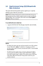
1.  Log into the Web GUI. The QIS page launches automatically.

NOTES

:

•  By default, the login username and password for your ADSL modem 

router's Web GUI is 

admin

. For details on changing your ADSL 

modem router's login username and password, refer to section 

4.2.4 

Access Control

.

•  The ADSL modem router's login username and password allows 

you to log into your ADSL modem router's Web GUI to configure 

your ADSL modem router's settings. The network name (SSID) and 

security key allows Wi-Fi devices to log in and connect to your 

wireless network.

Summary of Contents for DSL-N12HP

Page 1: ...DSL N12HP 300Mbps Wi Fi ADSL Modem Router User Guide ...

Page 2: ...TICULAR PURPOSE IN NO EVENT SHALL ASUS ITS DIRECTORS OFFICERS EMPLOYEES OR AGENTS BE LIABLE FOR ANY INDIRECT SPECIAL INCIDENTAL OR CONSEQUENTIAL DAMAGES INCLUDING DAMAGES FOR LOSS OF PROFITS LOSS OF BUSINESS LOSS OF USE OR DATA INTERRUPTION OF BUSINESS AND THE LIKE EVEN IF ASUS HAS BEEN ADVISED OF THE POSSIBILITY OF SUCH DAMAGES ARISING FROM ANY DEFECT OR ERROR IN THIS MANUAL OR PRODUCT SPECIFICAT...

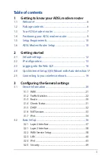
Page 3: ...guration 13 2 3 Logging into the Web GUI 16 2 4 Quick Internet Setup QIS Wizard with Auto detection 17 2 5 Connecting to your wireless network 19 3 Configuring the General settings 3 1 Device Information 20 3 1 1 WAN 21 3 1 2 Traffic Statistics 22 3 1 3 Route 30 3 1 4 Clients Status 31 3 1 5 DHCP 32 3 1 6 NAT Session 33 3 1 7 IPv6 34 3 2 Basic Setup 36 3 2 1 Layer 2 Interface 37 3 2 1 Layer 2 Inte...

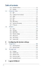
Page 4: ...P Tunnel 91 3 4 Wireless 95 3 4 1 Basic 96 3 4 2 Security 98 3 4 3 MAC Filter 101 3 4 4 Wireless Bridge 102 3 4 5 Advanced 103 3 4 6 Site Survey 106 3 4 7 Station Info 107 4 Configuring the System settings 4 1 Diagnostics 108 4 1 1 Individual Tests 108 4 1 2 Uptime Status 109 4 2 Management 110 4 2 1 Settings 110 4 2 2 System Log 113 4 2 3 Internet Time 115 4 2 4 Access Control 116 4 2 5 Update So...

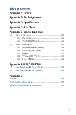
Page 5: ...es 132 E1 2 ETHERNET WAN Interfaces 135 E2 WAN Connections 137 E2 1 PPP over ETHERNET PPPoE 139 E2 2 IP over ETHERNET IPoE 145 E2 3 Bridging 151 E2 4 PPP over ATM PPPoA 153 E2 5 IP over ATM IPoA 158 Appendix F WPS OPERATION F1 Add Enrollee with Pin Method 162 F2 Add Enrollee with PBC Method 163 Appendix G Notices 164 ASUS Contact Information 178 Networks Global Hotline Information 179 ...

Page 6: ...odem Router DSL N12HP is an 802 11n 300Mbps Wireless ADSL2 router comprising four 10 100 Base T Ethernet ports a Wi Fi Protected Setup WPS Wi Fi switch button and is backward compatible with existing 802 11b 11Mbps and 11g 54bps equipment The DSL N12HP ADSL2 router provides state of the art security features such as 64 128 bit WEP encryption and WPA WPA2 encryption Firewall and VPN pass through 1 ...

Page 7: ...ould not occur ADSL LED Off No ADSL link or unable to establish ADSL link Solid green ADSL link is established Flashing green ADSL is attempting to connect to a DSLAM Internet LED Off IP connected and no traffic detected the device has a WAN IP address from IPCP or DHCP is up or a static IP address is configured PPP negotiation has successfully complete If the IP or PPPoE session is dropped due to...

Page 8: ... on off button Press and hold this button more than 5 seconds to activate WPS Ensure that the WPS is enabled in Wireless Security page Press and hold this button 2 3 seconds to enable disable Wi Fi ADSL port Connect to a splitter or to a telephone outlet via an RJ 11 cable LAN 1 4 ports Connect network cables into these ports to establish LAN connection Reset button Press this button for 10 second...

Page 9: ...ct sunlight To prevent signal interference or loss keep the device away from 802 11g or 20MHz only Wi Fi devices 2 4GHz computer peripherals Bluetooth devices cordless phones transformers heavy duty motors fluorescent lights microwave ovens refrigerators and other industrial equipment Always update to the latest firmware Visit the ASUS website at http www asus com to get the latest firmware update...

Page 10: ...ay install an IEEE 802 11b g n WLAN adapter to your computer to connect to the network The Ethernet RJ 45 cables that will be used to connect the network devices should not exceed 100 meters Wired connection NOTE You can use either a straight through cable or a crossover cable for wired connection 1 6 ADSL Modem Router Setup IMPORTANT Use a wired connection when setting up your ADSL modem router t...

Page 11: ...t of your splitter 2 Using a network cable connect your computer to your ADSL modem router s LAN port 3 Insert your ADSL modem router s power adapter to the DC IN port and plug it to a power outlet IMPORTANT After turning on your ADSL modem router wait for a few minutes for Internet connection 4 3 2 1 Wall telephone outlet Computer Wall Power Outlet Power LAN Splitter Phone DSL ...

Page 12: ...e admin password admin Wi Fi access enabled NOTE During power on the device initializes all settings to default values It will then read the configuration profile from the permanent storage section of flash memory The default attributes are overwritten when identical attributes with different values are configured The configuration profile in permanent storage can be created via the Web GUI or tel...

Page 13: ... follow the steps provided below NOTE The following procedure assumes you are running Windows 7 However the general steps involved are similar for most operating systems OS Check your OS support documentation for further details 1 Click Start Control Panel Network and Internet Network and Sharing Center Manage network connections 2 Select Internet Protocol Version 4 TCP IPv4 or Internet ProtocolVe...

Page 14: ...nce difficulty with DHCP mode you can try static IP mode instead STATIC IP MODE In static IP mode you assign IP settings to your PC manually Follow these steps to configure your PC IP address to use subnet 192 168 1 x NOTE The following procedure assumes you are running Windows 7 However the general steps involved are similar for most operating systems OS Check your OS support documentation for fu...

Page 15: ...ith subnet mask of 255 255 255 0 4 Click OK when done 1 Click Start Control Panel Network and Internet Network and Sharing Center Manage network connections 2 Select Internet Protocol Version 4 TCP IPv4 or Internet ProtocolVersion 6 TCP IPv6 then click Properties ...

Page 16: ...Device Information screen and login with remote username and password 2 On the login page key in the default user name admin and password admin NOTE For details on changing your ADSL modem router s login username and password refer to section 4 2 4 Access Control 3 You can now use the Web GUI to configure various settings of your ASUS ADSL modem router NOTE If you are logging into the Web GUI for ...

Page 17: ...is user manual To use QIS with auto detection 1 Log into the Web GUI The QIS page launches automatically NOTES By default the login username and password for your ADSL modem router s Web GUI is admin For details on changing your ADSL modem router s login username and password refer to section 4 2 4 Access Control The ADSL modem router s login username and password allows you to log into your ADSL ...

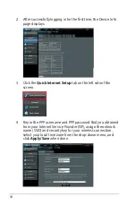
Page 18: ...ternet Setup tab on the left side of the screen 4 Key in the PPP username and PPP password that you obtained from your Internet Service Provider ISP assign the network name SSID and security key for your wireless connection select your local time zone from the drop down menu and click Apply Save when done ...

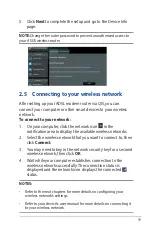
Page 19: ...the notification area to display the available wireless networks 2 Select the wireless network that you want to connect to then click Connect 3 You may need to key in the network security key for a secured wireless network then click OK 4 Wait while your computer establishes connection to the wireless network successfully The connection status is displayed and the network icon displays the connect...

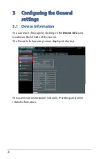
Page 20: ...evice Information You can reach this page by clicking on the Device Info icon located on the left side of the screen The Device Info Summary screen displays at startup This screen shows hardware software IP settings and other related information ...

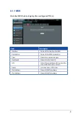
Page 21: ...the interface for WAN Description Name of the WAN connection Type Shows the connection type VlanMuxId Shows 802 1Q VLAN ID Info Shows the parameter setting value like IPv6 IGMP MLD NAT Firewall Status Lists the status of DSL link IPv4 Address Shows WAN IPv4 address IPv6 Address Shows WAN IPv6 address ...

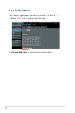
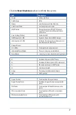
Page 22: ...22 3 1 2 Traffic Statistics This selection provides LAN WAN xTM and xDSL statistics Click the Traffic tab to display the following Click Reset Statistics to perform a manual update ...

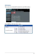
Page 23: ...ic statistics for each LAN interface Select LAN from the drop down menu Field Description Interface LAN interface s Received Transmitted Bytes Number of Bytes Pkts Number of Packets Errs Number of packets with errors Drops Number of dropped packets ...

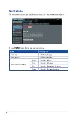
Page 24: ...or each WAN interface Select WAN from the drop down menu Field Description Interface WAN interface s Description WAN service label Received Transmitted Bytes Number of Bytes Pkts Number of Packets Errs Number of packets with errors Drops Number of dropped packets ...

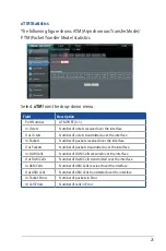
Page 25: ...mitted over the interface In Packets Number of packets received over the interface Out Packets Number of packets transmitted over the interface In OAM Cells Number of OAM Cells received over the interface Out OAM Cells Number of OAM Cells transmitted over the interface In ASM Cells Number of ASM Cells received over the interface Out ASM Cells Number of ASM Cells transmitted over the interface In P...

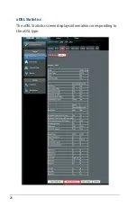
Page 26: ...26 xDSL Statistics The xDSL Statistics screen displays information corresponding to the xDSL type ...

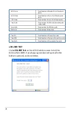
Page 27: ...wnstream direction Output Power 0 1 dBm Total upstream output power Attainable Rate Kbps The sync rate you would obtain Rate Kbps Current sync rates downstream upstream K Number of bytes in DMT frame R Number of check bytes in RS code word S RS code word size in DMT frame D Interleaver depth Delay The delay in milliseconds msec INP DMT symbol Super Frames Total number of super frames Super Frame E...

Page 28: ...ncluding idle data cells Data Cells Total number of ATM data cells Bit Errors Total number of bit errors Total ES Total Number of Errored Seconds Total SES Total Number of Severely Errored Seconds Total UAS Total Number of Unavailable Seconds xDSL BERTEST Click xDSL BERTest on the xDSL Statistics screen to test the Bit Error Rate BER A small pop up window will open after the button is pressed as s...

Page 29: ...st or click Close to cancel the test After the BER testing is complete the pop up window will display as follows xDSLTONE GRAPH Click Draw Graph on the xDSL Statistics screen and a pop up window will display the DSL line statistics ...

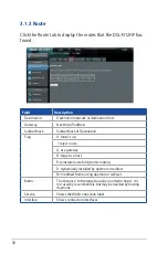
Page 30: ...f Destination Flag U route is up reject route G use gateway H target is a host R reinstate route for dynamic routing D dynamically installed by daemon or redirect M modified from routing daemon or redirect Metric The distance to the target usually counted in hops It is not used by recent kernels but may be needed by routing daemons Service Shows the WAN connection label Interface Shows connection ...

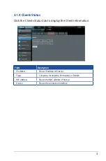
Page 31: ...lients Status tab to display the Client information Field Description IP address Shows IP address of host pc Flags Complete Incomplete Permanent or Publish HW Address Shows the MAC address of host pc Device Shows the connection interface ...

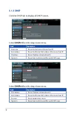
Page 32: ... address of the device host PC IP Address Shows IP address of device host PC Expires In Shows how much time is left for each DHCP Lease Select DHCPv6 from the drop down menu Field Description IPv6 Address Shows IP address of device host PC MAC Address Shows the Ethernet MAC address of the device host PC Duration Shows leased time in hours Expires In Shows how much time is left for each DHCP Lease ...

Page 33: ...h the NAT session is established Source Port The source port from which the NAT session is established Destination IP The IP which the NAT session was connected to Destination Port The port which the NAT session was connected to Protocol The Protocol used in establishing the particular NAT session Timeout The time remaining for the TCP UDP connection to be active ...

Page 34: ...ce with IPv6 enabled Status Connection status of the WAN interface Address IPv6 Address of the WAN interface Prefix Prefix received configured on the WAN interface Device Link local Address The CPE s LAN Address Default IPv6 Gateway The default WAN IPv6 gateway IPv6 DNS Server The IPv6 DNS servers received from the WAN interface configured manually ...

Page 35: ...Ipv6 address of the device s found Flags Status of the neighbor device HW Address MAC address of the neighbor device Device Interface from which the device is located Field Description Destination Destination IP Address Gateway Gateway address used for destination IP Metric Metric specified for gateway Interface Interface used for destination IP ...

Page 36: ...36 3 2 Basic Setup You can reach this page by clicking on the Basic Setup icon located on the left side of the screen This will bring you to the following screen ...

Page 37: ...TH WAN interface connections here Click Add to create a new ATM interface see Appendix E Connection Setup NOTE Up to 8 ATM interfaces can be created and saved in flash memory To remove a connection select its Remove column radio button and click Remove ...

Page 38: ...erface see Appendix E Connection Setup NOTE Up to 8 ATM interfaces can be created and saved in flash memory To remove a connection select its Remove column radio button and click Remove 3 2 2 WAN Service Setup This screen allows for the configuration of WAN interfaces Click the WAN Service tab to display the following ...

Page 39: ...MuxId Shows 802 1Q VLAN ID Igmp Shows Internet Group Management Protocol IGMP status NAT Shows Network Address Translation NAT status Firewall Shows the Security status IPv6 Shows the WAN IPv6 address MLD Shows Multicast Listener Discovery MLD status Remove Select interfaces to remove NOTES ETH and ATM service connections cannot coexist In Default Mode up to 8 WAN connections can be configured whi...

Page 40: ...ess Enter the IP address for the LAN port Subnet Mask Enter the subnet mask for the LAN port IGMP Snooping Standard Mode In standard mode multicast traffic will flood to all bridge ports when no client subscribes to a multicast group even if IGMP snooping is enabled Blocking Mode In blocking mode the multicast data traffic will be blocked and not flood to all bridge ports when there are no client ...

Page 41: ...s setting configures the router to automatically assign IP default gateway and DNS server addresses to every PC on your LAN SettingTFTP Server Enable by ticking the checkbox Then input the TFTP server address or an IP address Static IP Lease List A maximum of 32 entries can be configured To add an entry enter MAC address and Static IP address and then click Apply Save To remove an entry tick the c...

Page 42: ...ACE To configure a secondary IP address tick the checkbox outlined in RED below IP Address Enter the secondary IP address for the LAN port Subnet Mask Enter the secondary subnet mask for the LAN port Ethernet Media Type ...

Page 43: ...43 3 2 4 IPv6 Click the IPv6 tab to display the following ...

Page 44: ...44 LAN IPv6 Auto Configuration Select IPv6 LAN Auto Configuration from the drop down menu Configure the LAN interface settings and then click Save Apply ...

Page 45: ...atic LAN IPv6 address and subnet prefix length IPv6 LAN Applications Field Description Stateless Use stateless configuration Refresh Time sec The information refresh time option specifies how long a client should wait before refreshing information retrieved from DHCPv6 Stateful Use stateful configuration Start interface ID Start of interface ID to be assigned to dhcpv6 client End interface ID End ...

Page 46: ...46 To add an entry enter MAC address and Interface ID and then click Apply Save To remove an entry tick the corresponding checkbox in the Remove column and then click Remove Entries ...

Page 47: ...ngth preferred lifetime and valid lifetime used in router advertisement Enable ULA Prefix Advertisement Allow RADVD to advertise Unique Local Address Prefix Randomly Generate Use a Randomly Generated Prefix Statically Configure Prefix Specify the prefix to be used Statically Configure The prefix to be used Preferred Life Time hour The preferred life time for this prefix Valid Life Time hour The va...

Page 48: ...on to display the following Click Apply Save to apply and save the settings Field Description IP Version The IP version used for the neighbor device IP Address Define the IP Address for the neighbor device MAC Address The MAC Address of the neighbor device Associated Interface The interface where the neighbor device is located ...

Page 49: ...5 Security To display this function you must enable the firewall feature in WAN Setup For detailed descriptions with examples please consult Appendix A Firewall Click the Security tab to display the following ...

Page 50: ...ing condition For individual IP packets to pass the filter all conditions must be fulfilled NOTE This function is not available when in bridge mode Instead MAC Filtering performs a similar function Select IP Filtering Setup from the drop down menu INCOMING IP FILTER By default all incoming IP traffic is blocked but IP traffic can be allowed with filters ...

Page 51: ...DP or ICMP Policy Permit Drop packets specified by the firewall rule Source IP address Enter source IP address Source Port port or port port Enter source port number or range Destination IP address Enter destination IP address Destination Port port or port port Enter destination port number or range At the bottom of this screen select the WAN and LAN Interfaces to which the filter rule will apply ...

Page 52: ...a and then click Apply Save Consult the table below for field descriptions Field Description Filter Name The filter rule label IP Version Select from the drop down menu Protocol TCP TCP UDP UDP or ICMP Source IP address Enter source IP address Source Port port or port port Enter source port number or range Destination IP address Enter destination IP address Destination Port port or port port Enter...

Page 53: ...layer frames will be FORWARDED except those matching the MAC filter rules BLOCKED means that all MAC layer frames will be BLOCKED except those matching the MAC filter rules The default MAC Filtering Global policy is FORWARDED It can be changed by clicking the Change Policy button Select MAC Filtering Setup from the drop down menu Choose Add or Remove to configure MAC filtering rules The following ...

Page 54: ... Field Description Protocol Type PPPoE IPv4 IPv6 AppleTalk IPX NetBEUI IGMP Destination MAC Address Defines the destination MAC address Source MAC Address Defines the source MAC address Frame Direction Select the incoming outgoing packet interface WAN Interfaces Applies the filter to the selected bridge interface ...

Page 55: ...ng Time Restriction This feature restricts access from a LAN device to an outside network through the device on selected days at certain times Make sure to activate the Internet Time server synchronization as described in section Internet Time so that the scheduled times match your local time Select Time Restriction from the drop down menu ...

Page 56: ...s restriction Browser s MAC Address MAC address of the PC running the browser Other MAC Address MAC address of another LAN device Days of theWeek The days the restrictions apply Start BlockingTime The time the restrictions start End BlockingTime The time the restrictions end Click Apply Save to add a time restriction ...

Page 57: ...m the drop down menu Select the Deny radio button to deny access to the websites listed Select the Allow radio button to restrict access to only those listed websites Then click Add to display the following screen Enter the URL address and port number then click Apply Save to add the entry to the URL filter URL Addresses begin with www as shown in this example ...

Page 58: ...he following routing functions are accessed from this menu Default Gateway Static Route Policy Routing RIP and IPv6 Static Route NOTE In bridge mode the RIP menu option is hidden while the other menu options are shown but ineffective Click the Routing tab to display the following ...

Page 59: ...can have multiple WAN interfaces served as system default gateways but only one will be used according to the priority with the first being the highest and the last one the lowest priority if the WAN interface is connected Priority order can be changed by removing all and adding them back in again ...

Page 60: ...rom the drop down menu Click Add to display the following screen IPVersion Select the IP version to be IPv4 Destination IP address prefix length Enter the destination IP address Interface select the proper interface for the rule Gateway IP Address The next hop IP address Metric The metric value of routing After completing the settings click Apply Save to add the entry to the routing table ...

Page 61: ... entry Click Add to display the following Complete the form and click Apply Save to create a policy Field Description Policy Name Name of the route policy Physical LAN Port Specify the port to use this route policy Source IP IP Address to be routed Use Interface Interface that traffic will be directed to Default Gateway IP IP Address of the default gateway ...

Page 62: ...p down menu To activate RIP for the WAN Interface select the desired RIP version and operation and place a check in the Enabled checkbox To stop RIP on the WAN Interface uncheck the Enabled checkbox Click Apply Save to start stop RIP and save the configuration ...

Page 63: ...dvanced Setup icon located on the left side of the screen This will bring you to the following screen 3 3 1 NAT NOTE To display this option NAT must be enabled in at least one PVC NAT is not an available option in Bridge mode Click the NAT tab to display the following ...

Page 64: ...al server with private IP addresses on the LAN side The Internal port is required only if the external port needs to be converted to a different port number used by the server on the LAN side A maximum of 32 entries can be configured Select Virtual Servers from the drop down menu To add a Virtual Server click Add The following will be displayed ...

Page 65: ...ing external port number when you select Custom Server When a service is selected the port ranges are automatically configured External Port End Enter the ending external port number when you select Custom Server When a service is selected the port ranges are automatically configured Protocol TCP TCP UDP or UDP Internal Port Start Enter the internal port starting number when you select Custom Serv...

Page 66: ...plication on the LAN initiates a TCP UDP connection to a remote party using the Triggering Ports The Router allows the remote party from the WAN side to establish new connections back to the application on the LAN side using the Open Ports A maximum 32 entries can be configured Select PortTriggering from the drop down menu To add a Trigger Port click Add The following will be displayed ...

Page 67: ...ication is selected the port ranges are automatically configured Trigger Port End Enter the ending trigger port number when you select custom application When an application is selected the port ranges are automatically configured Trigger Protocol TCP TCP UDP or UDP Open Port Start Enter the starting open port number when you select custom application When an application is selected the port range...

Page 68: ...Z host computer Select DMZ Host from the drop down menu Click Save Apply to save and apply the settings To Activate the DMZ host enter the DMZ host IP address and click Save Apply To Deactivate the DMZ host clear the IP address field and click Save Apply Enable NAT Loopback allows PC on the LAN side to access servers in the LAN network via the router s WAN IP ...

Page 69: ...Public Start IP The beginning of the public IP Public End IP The ending of the public IP Remove Remove this rule Click the Add button to display the following Select a Service then click the Save Apply button One to One mapping one local IP to a specific public IP Many to one mapping a range of local IP to a specific public IP Many to many Overload mapping a range of local IP to a different range ...

Page 70: ...on LAN side to establish a secured IP Connection to the WAN server Select IPSEC ALG from the drop down menu To enable IPSEC ALG tick the checkbox and click Save SIP ALG This page allows you to enable disable SIP ALG Select SIP ALG from the drop down menu To enable SIP ALG tick the checkbox and click Save ...

Page 71: ... 3 2 Quality of Service QoS NOTE QoS must be enabled in at least one PVC to display this option See Appendix E Connection Setup for detailed PVC setup instructions Click the QoS tab to display the following ...

Page 72: ...ed as follows Quality of Service QoS This provides different priority to different users or data flows or guarantees a certain level of performance to a data flow in accordance with requests from Queue Prioritization Default Differentiated Services Code Point DSCP Mark This specifies the per hop behavior for a given flow of packets in the Internet Protocol IP header that do not match any other QoS...

Page 73: ...ues can be configured In PTM mode maximum 8 queues can be configured For each Ethernet interface maximum 3 queues can be configured Select QoS Queue Setup from the drop down menu To add a queue click the Add button To remove queues check their remove checkboxes for user created queues then click the Remove button ...

Page 74: ...ed to wireless will not take effect This function follows the Differentiated Services rule of IP QoS You can create a new Queue entry by clicking the Add button Enable and assign an interface and precedence on the next screen Click Save Reboot on this screen to activate it Click Apply Save to apply and save the settings Name Identifier for this Queue entry Enable Enable Disable the Queue entry Int...

Page 75: ...xes then click the Remove button The Enable button will scan through every policers in the table Policers with enable checkbox checked will be enabled Policers with enable checkbox un checked will be disabled The enable checkbox also shows status of the policer after page reload To add a policer click the Add button ...

Page 76: ...ype used for this policer rule Committed Rate kbps Defines the rate allowed for committed packets Committed Burst Size bytes Maximum amount of packets that can be processed by this policer Conforming Action Defines action to be taken if packets match this policer Nonconforming Action Defines actions to be taken if packets do not match this policer ...

Page 77: ...affic class rule and Enable to activate it To delete an entry from the list click Remove This screen creates a traffic class rule to classify the upstream traffic assign queuing priority and optionally overwrite the IP header DSCP byte A rule consists of a class name and at least one logical condition All the conditions specified in the rule must be satisfied for it to take effect ...

Page 78: ...assification Criteria Class Interface Select an interface i e Local eth0 4 wl0 Ether Type Set the Ethernet type e g IP ARP IPv6 Source MAC Address A packet belongs to SET 1 if a binary AND of its source MAC address with the Source MAC Mask is equal to the binary AND of the Source MAC Mask and this field Source MAC Mask This is the mask used to decide how many bits are checked in Source MAC Address...

Page 79: ...classified into a queue that exit through an interface for which the queue is not specified to exist will instead egress to the default queue on the interface Specify Class Policer Packets classified into a policer will be marked based on the conforming action of the policer Mark Differentiated Service Code Point The selected Code Point gives the corresponding priority to packets that satisfy the ...

Page 80: ...80 3 3 4 DNS Click the DNS tab to display the following ...

Page 81: ... Interfaces can have multiple WAN interfaces served as system DNS servers but only one will be used according to the priority with the first being the highest and the last one the lowest priority if the WAN interface is connected Priority order can be changed by removing all and adding them back in again Select DNS Server Configuration from the drop down menu Click Apply Save to save the new confi...

Page 82: ...amic IP address to a static hostname in any of many domains allowing the DSL N12HP to be more easily accessed from various locations on the Internet Select Dynamic DNS from the drop down menu To add a dynamic DNS service click Add The following screen will display ...

Page 83: ...elect the interface from the list Username Enter the username of the dynamic DNS server Password Enter the password of the dynamic DNS server Email Enter mail server for DDNS Key Enter an account level key which can be used to update DNS hosts instead of our HTTP based DNS update API DynDNS Server Enter dynamic DNS server URL Address Dynamic DNS server URL Username Dynamic DNS server name Password...

Page 84: ...s desired to be resolved by the DSL router Select Dynamic DNS from the drop down menu Choose Add or Remove to configure DNS Entry The entries will become active after save reboot Enter the domain name and IP address that needs to be resolved locally and click the Add Entry button ...

Page 85: ...he following DSL Mode DataTransmission Rate Mbps Megabits per second G Dmt Downstream 12 Mbps Upstream 1 3 Mbps G lite Downstream 4 Mbps Upstream 0 5 Mbps T1 413 Downstream 8 Mbps Upstream 1 0 Mbps ADSL2 Downstream 12 Mbps Upstream 1 0 Mbps AnnexL Supports longer loops but with reduced transmission rates ADSL2 Downstream 24 Mbps Upstream 1 0 Mbps AnnexM Downstream 24 Mbps Upstream 3 5 Mbps ...

Page 86: ... Number or Equipment MAC Address to use router s serial number or MAC address in ADSL EOC messages Advanced DSL Settings Click Advanced Settings to reveal additional options On this screen you select the required test mode then click the Apply button Field Description Normal DSL line signal is detected and sent normally Reverb DSL line signal is sent continuously in reverb mode Medley DSL line sig...

Page 87: ...S server it replies to the LAN clients Configure DNS proxy with the default setting when the PC gets an IP via DHCP the domain name Home will be added to PC s DNS Suffix Search List and the PC can access route with ASUS Home Click the DNS Proxy tab to display the following Click Apply Save to implement new configuration settings ...

Page 88: ...ropriate LAN and WAN interfaces using the Add button The Remove button removes mapping groups returning the ungrouped interfaces to the Default group Only the default group has an IP interface Click the Interface Grouping tab to display the following To add an Interface Group click Add The following screen will appear It lists the available and grouped interfaces Follow the instructions shown onsc...

Page 89: ...89 Click Apply Save to implement new configuration settings ...

Page 90: ... and LAN4 The Interface Grouping configuration will be 1 Default LAN1 LAN2 LAN3 and LAN4 2 Video nas_0_36 nas_0_37 and nas_0_38 The DHCP vendor ID is Video If the onboard DHCP server is running on Default and the remote DHCP server is running on PVC 0 36 i e for set top box use only LAN side clients can get IP addresses from the CPE s DHCP server and access the Internet via PPPoE 0 33 If a set top...

Page 91: ...nnel Click on the IP Tunnel tab to display the following IPv6inIPv4 Configure 6in4 tunneling to encapsulate IPv6 traffic over explicitly configured IPv4 links Select 6in4Tunnel Configuration from the drop down menu ...

Page 92: ...ed WAN Interface Select the WAN interface to be used by the tunnel Associated LAN Interface Select the LAN interface to be included in the tunnel Manual Automatic Select automatic for point to multipoint tunneling manual for point to point tunneling IPv4 Mask Length The subnet mask length used for the IPv4 interface 6rd Prefix with Prefix Length Prefix and prefix length used for the IPv6 interface...

Page 93: ...late IPv4 traffic over an IPv6 only environment Select 4in6Tunnel Configuration from the drop down menu Click the Add button to display the following Click Apply Save to implement new configuration settings Click Return to go back to the previous page ...

Page 94: ...nt Associated WAN Interface Select the WAN interface to be used by the tunnel Associated LAN Interface Select the LAN interface to be included in the tunnel Manual Automatic Select automatic for point to multipoint tunneling manual for point to point tunneling AFTR Address of Address Family Translation Router ...

Page 95: ...95 3 4 Wireless You can reach this page by clicking the Wireless icon located on the left side of the screen ...

Page 96: ...other things you can enable or disable the wireless LAN interface hide the network from active scans set the wireless network name also known as SSID and restrict the channel set based on country requirements Click the Basic tab to display the following Click Apply Save to apply the selected wireless options ...

Page 97: ...entity used to identify a particular BSS Basic Service Set within an area In Infrastructure BSS networks the BSSID is the MAC Media Access Control address of the AP Access Point and in Independent BSS or ad hoc networks the BSSID is generated randomly Country A drop down menu that permits worldwide and specific national settings Local regulations limit channel range US worldwide Japan 1 14 Jordan ...

Page 98: ...onfigure security features of the wireless LAN interface Click the Security tab to display the following Please see Appendix F for WPS setup instructions Click Apply Save to implement new configuration settings WIRELESS SECURITY Setup requires that the user configure these settings using the Web GUI see the table below ...

Page 99: ...network key is used for authentication to the wireless network If network authentication is set to Open then no authentication is provided Despite this the identity of the client is still verified Each authentication type has its own settings For example selecting 802 1X authentication will reveal the RADIUS Server IP address Port and Key fields WEP Encryption will also be enabled as shown below T...

Page 100: ... the destination station to alter frame bits thus avoiding disclosure to eavesdroppers Under shared key authentication each wireless station is assumed to have received a secret shared key over a secure channel that is independent from the 802 11 wireless network communications channel Encryption Strength This drop down list box will display when WEP Encryption is enabled The key strength is propo...

Page 101: ...ations must be configured with the correct SSID to access the WLAN If the SSID does not match that user will not be granted access MAC Restrict Mode Disabled MAC filtering is disabled Allow Permits access for the specified MAC addresses Deny Rejects access for the specified MAC addresses MAC Address Lists the MAC addresses subject to the MAC Restrict Mode A maximum of 60 MAC addresses can be added...

Page 102: ...ystem disables Access Point AP functionality while selecting Access Point enables AP functionality In Access Point mode wireless bridge functionality will still be available and wireless stations will be able to associate to the AP Bridge Restrict Selecting Disabled disables wireless bridge restriction which means that any wireless bridge will be granted access Selecting Enabled or Enabled Scan en...

Page 103: ...e the transmission rate to a particular speed set the fragmentation threshold set the RTS threshold set the wakeup interval for clients in power save mode set the beacon interval for the access point set XPress mode and set whether short or long preambles are used Click the Wireless Bridge tab to display the following Click Apply Save to set new advanced wireless options ...

Page 104: ...r security Support 802 11n Client Only Turn Off to allow 802 11b g clients access to the router Turn On to prohibit 802 11b g client s access to the router RIFS Advertisement One of several draft n features designed to improve efficiency Provides a shorter delay between OFDM transmissions than in802 11a or g OBSS Co Existence Co existence between 20 MHZ AND 40 MHZ overlapping Basic Service Set OBS...

Page 105: ...icast messages When the AP has buffered broadcast or multicast messages for associated clients it sends the next DTIM with a DTIM Interval value AP Clients hear the beacons and awaken to receive the broadcast and multicast messages The default is 1 Beacon Interval The amount of time between beacon transmissions in milliseconds The default is 100 ms and the acceptable range is 1 65535 The beacon tr...

Page 106: ...106 3 4 6 Site Survey The graph displays wireless APs found in your neighborhood by channel Click the Site Survey tab to display the following ...

Page 107: ...ld Description MAC Lists the MAC address of all the stations Associated Lists all the stations that are associated with the Access Point along with the amount of time since packets were transferred to and from each station If a station is idle for too long it is removed from this list Authorized Lists those devices with authorized access SSID Lists which SSID of the modem that the stations connect...

Page 108: ...ndividualTests The first Diagnostics screen is a dashboard that shows overall connection status Click the Diagnostics tab to display the following If a test displays a fail status click Rerun Diagnostic Tests at the bottom of this page to make sure the fail status is consistent If the test continues to fail click Help and follow the troubleshooting procedures ...

Page 109: ...n is down the uptime will stop incrementing If the service is restored the counter will reset and start from 0 A Bridge interface will follow the DSL or ETH timer Click the Uptime Status tab to display the following The ClearAll button will restart the counters from 0 or show Not Connected if the interface is down ...

Page 110: ... reach this page by clicking on the Management icon located on the left side of the screen 4 2 1 Settings Click on the Settings tab to display the following This includes Restore Default Save Setting and Restore Setting screens ...

Page 111: ...r 2 minutes before reopening it It may also be necessary to reconfigure your PC IP configuration to match any new settings NOTE This entry has the same effect as the Reset button The DSL N12HP board hardware and the boot loader support the reset to default If the Reset button is continuously pressed for more than 10 seconds the boot loader will erase the configuration data saved in flash memory ...

Page 112: ...ted for backup file location This file can later be used to recover settings on the Restore Setting screen as described below Upload Setting This option recovers configuration files previously saved using Save Setting Press the Browse button to search for the file then click the Upload button to restore settings ...

Page 113: ...values and click Apply Save to configure the system log options Consult the table below for detailed descriptions of each system log option Field Description Log Indicates whether the system is currently recording events The user can enable or disable event logging By default it is disabled To enable it select the Enable radio button and then click Apply Save ...

Page 114: ...debug level messages Emergency is the most serious event level whereas Debugging is the least important For instance if the log level is set to Debugging all the events from the lowest Debugging level to the most critical level Emergency level will be recorded If the log level is set to Error only Error and the level above will be logged Display Level Allows the user to select the logged events an...

Page 115: ...wing To enable time synchronization tick the corresponding checkbox choose your preferred time server s select the correct time zone offset and click Apply Save NOTE Internet Time must be activated to use Parental Control In addition this menu item is not displayed when in Bridge mode since the router would not be able to connect to the NTP timeserver ...

Page 116: ...configure the user account access passwords for the device Select Access Control Accounts Passwords from the drop down menu Use the fields to update passwords for the accounts administration NOTE Passwords may be as long as 16 characters but must not contain a space Click Apply Save to apply and save the settings ...

Page 117: ...ens the access services over the LAN or WAN Select Access Control Service Access from the drop down menu These access services available are HTTP SSH TELNET HTTPS and ICMP Enable a service by selecting its drop down list box Click Apply Save to activate ...

Page 118: ...Service Control List beside ICMP Select Access Control IP Address from the drop down menu Configure the address and subnet of the management station permitted to access the local management services and click Save Apply IP Address IP address of the management station Subnet Mask Subnet address for the management station Interface Access permission for the specified address allowing the address to ...

Page 119: ...lt configuration after software upgrade Erase All Router will be restored to factory default configuration after software upgrade 3 Enter the path to the image file location in the box below or click the Browse button to locate the image file 4 Click the Update Software button once to upload and install the file NOTE The update process will take about 2 minutes to complete The device will reboot a...

Page 120: ...uggestions or connection issue complete the form below these information along with current DSL logs will be send to ASUS Support Team In order to allow us to respond to your feedback kindly ensure that you have entered your e mail correctly Click the Feedback tab to display the following Upon completing the form click Send to submit ...

Page 121: ...t To log out from the device simply click the Logout button at the top of your screen When the following window pops up click the OK button to exit the router Upon successful exit the following message will be displayed ...

Page 122: ...122 To reboot the device simply click the Reboot button at the top of your screen While rebooting the following message will be displayed ...

Page 123: ...ttack Ping Attack Ping of Death Land SYN Attack Smurf Attack and Tear Drop TCP IP PORT INTERFACE FILTER These rules help in the filtering of traffic at the Network layer i e Layer 3 When a Routing interface is created Enable Firewall must be checked Navigate to Advanced Setup Security IP Filtering OUTGOING IP FILTER Helps in setting rules to DROP packets from the LAN interface By default if the Fi...

Page 124: ... packets coming from the LAN with IP Address Subnet Mask of 192 168 1 45 24 and a source port range of 5060 to 6060 destined to 172 16 13 4 24 and a destination port range of 6060 to 7070 INCOMING IP FILTER Helps in setting rules to Allow or Deny packets from the WAN interface By default all incoming IP traffic from the WAN is Blocked if the Firewall is Enabled By setting up one or more filters sp...

Page 125: ...rt 6060 7070 Selected WAN interface br0 This rule will ACCEPT all UDP packets coming from WAN interface br0 with IP Address Subnet Mask 210 168 219 45 16 and a source port in the range of 5060 to 6060 destined to 192 168 1 45 24 and a destination port in the range of 6060 to 7070 All other incoming packets on this interface are DROPPED MAC LAYER FILTER These rules help in the filtering of Layer 2 ...

Page 126: ...ith a Destination MAC Address of 00 12 34 56 78 and Source MAC Address of 00 34 12 78 90 56 All other frames on this interface are dropped DAYTIME PARENTAL CONTROL This feature restricts access of a selected LAN device to an outside Network through the DSL N12HP as per chosen days of the week and the chosen times Example User Name FilterJohn Browser s MAC Address 00 25 46 78 63 21 Days of the Week...

Page 127: ...Signal definition 1 TRD 0 Transmit Receive data 0 positive lead 2 TRD 0 Transmit Receive data 0 negative lead 3 TRD 1 Transmit Receive data 1 positive lead 4 TRD 2 Transmit Receive data 2 positive lead 5 TRD 2 Transmit Receive data 2 negative lead 6 TRD 1 Transmit Receive data 1 negative lead 7 TRD 3 Transmit Receive data 3 positive lead 8 TRD 3 Transmit Receive data 3 negative lead DSL Port Table...

Page 128: ...Upstream up to 1 3 Mbps ITU T G 992 5 ITU T G 992 3 ITU T G 992 1 ANSI T1 413 Issue 2 Annex A L M LAN Interface Standard IEEE 802 3 IEEE 802 3u Support MDI MDX 10 100 Base T Auto sense Wireless Interface IEEE802 11b g n 64 128 bit Wired Equivalent Privacy WEP Data Encryption WDS WEP WPA WPA2 Management Remote upgrade TFTP FTP upgrade Telnet remote access support Support Web based configuration Sup...

Page 129: ...nning Tree Algorithm IGMP Proxy V1 V2 V3 IGMP Snooping V1 V2 V3 Fast leave Static route RIP v1 v2 ARP RARP SNTP DHCP Server Client Relay DNS Proxy Relay Dynamic DNS UPnP IGD v1 0 IPv6 subset Security Functions PAP CHAP Packet and MAC address filtering SSH VPN termination Three level login including local admin local user and remote technical support access QoS Packet level QoS classification rules...

Page 130: ... rules Support both incoming and outgoing filtering NAT NAPT Support Port Triggering and Port forwarding Symmetric port overloading NAT Full Cone NAT Dynamic NAPT NAPT N to 1 Support DMZ host Virtual Server Port forwarding VPN Passthrough PPTP L2TP IPSec Application Passthrough PPTP L2TP IPSec Yahoo messenger ICQ RealPlayer NetMeeting MSN X box etc NOTE Specifications are subject to change without...

Page 131: ... first enable SSH access for the LAN or WAN from the Management Access Control Services menu in the Web GUI To access the router using the Linux ssh client For LAN access type ssh l root 192 168 1 1 For WAN access type ssh l support WAN IP address To access the router using the Windows putty ssh client For LAN access type putty ssh l root 192 168 1 1 For WAN access type putty ssh l support WAN IP ...

Page 132: ...ibe each stage in turn E1 Layer 2 Interfaces Every layer2 interface operates in Multi Service Connection VLAN MUX mode which supports multiple connections over a single interface Note that PPPoA and IPoA connection types are not supported for Ethernet WAN interfaces After adding WAN connections to an interface you must also create an Interface Group to connect LAN WAN interfaces E1 1ATM Interfaces...

Page 133: ...ency Path0 portID 0 Path1 port ID 1 Path0 1 port ID 4 Category ATM service category Max Burst Size The maximum allowable burst size of cells that can be transmitted contiguously on the VBR service connection Link Type Choose EoA for PPPoE IPoE and Bridge PPPoA or IPoA Connection Mode Default Mode Single service over one connection Vlan Mux Mode Multiple Vlan service over one connection IP QoS Qual...

Page 134: ...ncapsulation Mode Service Category Connection Mode and Quality of Service Here are the available encapsulations for each xDSL Link Type EoA LLC SNAP BRIDGING VC MUX PPPoA VC MUX LLC ENCAPSULATION IPoA LLC SNAP ROUTING VC MUX 2 Click Apply Save to confirm your choices ...

Page 135: ...WAN Connections E1 2ETHERNETWAN Interfaces Follow these procedures to configure an Ethernet WAN interface 1 Click Add to create an Ethernet WAN interface This table is provided here for ease of reference Field Description Interface Name WAN interface name Connection Mode Default Mode Single service over one interface Vlan Mux Mode Multiple Vlan services over one interface Remove Select interfaces ...

Page 136: ...136 2 Select an Ethernet port and Click Apply Save to confirm your choices On the next screen check that the ETHERNET interface is added to the list ...

Page 137: ...maximum of 16 connections 1 Click the WAN Service tab to display the following 2 Click the Add button to create a WAN connection The following screen will display 3 Choose a layer 2 interface from the drop down box and click Next The WAN Service Configuration screen will display as shown below ...

Page 138: ...you must enter Priority VLAN ID tags 5 You will now follow the instructions specific to the WAN service type you wish to establish This list should help you locate the correct procedure 1 For PPP over ETHERNET PPPoE go to page 134 2 For IP over ETHERNET IPoE go to page 139 3 For Bridging go to page 144 4 For PPP over ATM PPPoA go to page 145 5 For IP over ATM IPoA go to page 149 The subsections th...

Page 139: ...er Ethernet radio button and click Next You can also enable IPv6 by ticking the checkbox at the bottom of this screen 2 On the next screen enter the PPP settings as provided by your ISP Click Next to continue or click Back to return to the previous step ...

Page 140: ...rname PPP password and the PPPoE Service Name entries are dependent on the particular requirements of the ISP The user name can be a maximum of 256 characters and the password a maximum of 32 characters in length For Authentication Method choose from AUTO PAP CHAP and MSCHAP ...

Page 141: ...e provider specifically requires this setup do not select it PPP IP Extension does the following Allows only one PC on the LAN Disables NAT and Firewall The device becomes the default gateway and DNS server to the PC through DHCP using the LAN interface IP address The device extends the IP subnet at the remote service provider to the LAN PC i e the PC becomes a host belonging to the same IP subnet...

Page 142: ...IC IPv4 ADDRESS Unless your service provider specially requires it do not select this checkbox If selected enter the static IP address in the IPv4 Address field Don t forget to adjust the IP configuration to Static IP Mode as described in section 2 2 IP configuration FIXED MTU Maximum Transmission Unit The size in bytes of largest protocol data unit which the layer can pass onwards This value is 1...

Page 143: ...lticast routers NO MULTICASTVLAN FILTER Tick the checkbox to Enable Disable multicast VLAN filter Enable WAN interface with base MAC Enable this option to use the router s base MAC address as the MAC address for this WAN interface 3 Choose an interface to be the default gateway Click Next to continue or click Back to return to the previous step Select DNS Server Interface from available WAN interf...

Page 144: ... shows a preview of the WAN service you have configured Check these settings and click Apply Save if they are correct or click Back to modify them After clicking Apply Save the new service should appear on the main screen To activate it you must click the Reboot button at the top of the screen to reboot ...

Page 145: ...er ETHERNET IPoE 1 Select the IP over Ethernet radio button and click Next NOTE For tagged service enter valid 802 1P Priority and 802 1Q VLAN ID For untagged service set 1 to both 802 1P Priority and 802 1Q VLAN ID ...

Page 146: ...tatic IP address method to assign WAN IP address Subnet Mask and Default Gateway manually Click Next to continue or click Back to return to the previous step If IPv6 is enabled the following will also be shown Enter information provided to you by your ISP to configure the WAN IPv6 settings If Use the following Static IPv6 address is chosen enter the static WAN IPv6 address If the address prefix le...

Page 147: ... public IP this checkbox should not be selected so as to free up system resources for improved performance ENABLE FULLCONE NAT This option becomes available when NAT is enabled Known as one to one NAT all requests from the same internal IP address and port are mapped to the same external IP address and port An external host can send a packet to the internal host by sending a packet to the mapped e...

Page 148: ...hosts to report their multicast group memberships to any neighboring multicast routers EnableWAN interface with base MAC Enable this option to use the router s base MAC address as the MAC address for this WAN interface 4 To choose an interface to be the default gateway Click Next to continue or click Back to return to the previous step ...

Page 149: ...In ATM mode if only a single PVC with IPoA or static IPoE protocol is configured Static DNS server IP addresses must be entered If IPv6 is enabled the following will also be shown IPv6 Select a preferred wan interface as the system default IPv6 gateway Click Next to continue or click Back to return to the previous step ...

Page 150: ...e you have configured Check these settings and click Apply Save if they are correct or click Back to modify them After clicking Apply Save the new service should appear on the main screen To activate it you must click the Reboot button at the top of the screen to reboot ...

Page 151: ... E2 3Bridging 1 Select the Bridging radio button and click Next NOTE For tagged service enter valid 802 1P Priority and 802 1Q VLAN ID For untagged service set 1 to both 802 1P Priority and 802 1Q VLAN ID ...

Page 152: ... or click Back to return to the previous screen After clicking Apply Save the new service should appear on the main screen To activate it you must click the Reboot button at the top of the screen to reboot NOTE If this bridge connection is your only WAN service the DSL N12HP will be inaccessible for remote management or technical support from the WAN ...

Page 153: ...153 E2 4PPP over ATM PPPoA 1 Click Next to continue 2 On the next screen enter the PPP settings as provided by your ISP Click Next to continue or click Back to return to the previous step ...

Page 154: ... N12HP can be configured to disconnect if there is no activity for a period of time by selecting the Dial on demand checkbox You must also enter an inactivity timeout period in the range of 1 to 4320 minutes PPP IP EXTENSION The PPP IP Extension is a special feature deployed by some service providers Unless your service provider specifically requires this setup do not select it PPP IP Extension do...

Page 155: ... selected to free up system resources for better performance ENABLE FIREWALL If this checkbox is selected the Security submenu will be displayed on the Advanced Setup menu after reboot If firewall is not necessary this checkbox should not be selected to free up system resources for better performance USE STATIC IPv4 ADDRESS Unless your service provider specially requires it do not select this chec...

Page 156: ... memberships to any neighboring multicast routers NO MULTICASTVLAN FILTER Tick the checkbox to Enable Disable multicast VLAN filter EnableWAN interface with base MAC Enable this option to use the router s base MAC address as the MAC address for this WAN interface 3 Choose an interface to be the default gateway Click Next to continue or click Back to return to the previous step ...

Page 157: ...WAN Setup Summary screen shows a preview of the WAN service you have configured Check these settings and click Apply Save if they are correct or click Back to modify them After clicking Apply Save the new service should appear on the main screen To activate it you must click the Reboot button at the top of the screen to reboot ...

Page 158: ...r the WAN IP settings provided by your ISP Click Next to continue 3 This screen provides access to NAT Firewall and IGMP Multicast settings Enable each by selecting the appropriate checkbox Click Next to continue or click Back to return to the previous step ...

Page 159: ...he same external IP address and port An external host can send a packet to the internal host by sending a packet to the mapped external address ENABLE FIREWALL If this checkbox is selected the Security submenu will be displayed on the Advanced Setup menu after reboot If firewall is not necessary this checkbox should not be selected so as to free up system resources for better performance ENABLE IG...

Page 160: ...nterface to be the default gateway Click Next to continue or click Back to return to the previous step Click Next to continue or click Back to return to the previous step 5 Choose an interface to be the default gateway ...

Page 161: ...e you have configured Check these settings and click Apply Save if they are correct or click Back to modify them After clicking Apply Save the new service should appear on the main screen To activate it you must click the Reboot button at the top of the screen to reboot ...

Page 162: ...ation procedure F1 Add Enrollee with Pin Method 1 Click on the Wireless tab on the left side of your screen Then click on the Security tab to display the following 2 Select Enabled from the Enable WPS drop down menu Click the Apply Save button at the bottom of the screen ...

Page 163: ... example 5 Click Add Enrollee 6 Operate Station to start WPS Adding Enrollee F2 Add Enrollee with PBC Method 1 Press the WPS Wi Fi button on the back panel of the router to activate WPS PBC operation 2 Operate Station your dongle for example to start WPS Adding Enrollee 3 Press more than 5 seconds to trigger WPS 4 3 2 1 ...

Page 164: ...estriction of Chemicals regulatory framework we published the chemical substances in our products at ASUS REACH website at http csr asus com english index aspx Federal Communications Commission Statement This device complies with Part 15 of the FCC Rules Operation is subject to the following two conditions This device may not cause harmful interference This device must accept any interference rece...

Page 165: ...rient or relocate the receiving antenna Increase the separation between the equipment and receiver Connect the equipment into an outlet on a circuit different from that to which the receiver is connected Consult the dealer or an experienced radio TV technician for help IMPORTANT This device within the 5 15 5 25 GHz is restricted to indoor operations to reduce any potential for harmful interference...

Page 166: ...c compatibility Article 3 1b Testing for electromagnetic compatibility according to EN 301 489 1 and EN 301 489 17 has been conducted These are considered relevant and sufficient Effective use of the radio spectrum Article 3 2 Testing for radio test suites according to EN 300 328 EN 301 893 have been conducted These are considered relevant and sufficient Operate the device in 5150 5250 MHz frequen...

Page 167: ...ential for human contact during normal operation is minimized This device has been evaluated for and shown compliant with the IC Specific Absorption Rate SAR limits when installed in specific host products operated in portable exposure conditions antennas are less than 20 centimeters of a person s body This device has been certified for use in Canada Status of the listing in the Industry Canada s ...

Page 168: ...l Public License Licensing information This product includes copyrighted third party software licensed under the terms of the GNU General Public License Please see The GNU General Public License for the exact terms and conditions of this license We include a copy of the GPL with every CD shipped with our product All future firmware updates will also be accompanied with their respective source code...

Page 169: ...tware we are referring to freedom not price Our General Public Licenses are designed to make sure that you have the freedom to distribute copies of free software and charge for this service if you wish that you receive source code or can get it if you want it that you can change the software or use pieces of it in new free programs and that you know you can do these things To protect your rights w...

Page 170: ...revent this we have made it clear that any patent must be licensed for everyone s free use or not licensed at all The precise terms and conditions for copying distribution and modification follow Terms conditions for copying distribution modification 0 This License applies to any program or other work which contains a notice placed by the copyright holder saying it may be distributed under the ter...

Page 171: ...ction in exchange for a fee 2 You may modify your copy or copies of the Program or any portion of it thus forming a work based on the Program and copy and distribute such modifications or work under the terms of Section 1 above provided that you also meet all of these conditions a You must cause the modified files to carry prominent notices stating that you changed the files and the date of any ch...

Page 172: ... of this section to claim rights or contest your rights to work written entirely by you rather the intent is to exercise the right to control the distribution of derivative or collective works based on the Program In addition mere aggregation of another work not based on the Program with the Program or with a work based on the Program on a volume of a storage or distribution medium does not bring ...

Page 173: ... kernel and so on of the operating system on which the executable runs unless that component itself accompanies the executable If distribution of executable or object code is made by offering access to copy from a designated place then offering equivalent access to copy the source code from the same place counts as distribution of the source code even though third parties are not compelled to copy...

Page 174: ...e they do not excuse you from the conditions of this License If you cannot distribute so as to satisfy simultaneously your obligations under this License and any other pertinent obligations then as a consequence you may not distribute the Program at all For example if a patent license would not permit royalty free redistribution of the Program by all those who receive copies directly or indirectly...

Page 175: ... such case this License incorporates the limitation as if written in the body of this License 9 The Free Software Foundation may publish revised and or new versions of the General Public License from time to time Such new versions will be similar in spirit to the present version but may differ in detail to address new problems or concerns Each version is given a distinguishing version number If th...

Page 176: ...RRANTIES OF MERCHANTABILITY AND FITNESS FOR A PARTICULAR PURPOSE THE ENTIRE RISK AS TO THE QUALITY AND PERFORMANCE OF THE PROGRAM IS WITHYOU SHOULD THE PROGRAM PROVE DEFECTIVE YOU ASSUME THE COST OF ALL NECESSARY SERVICING REPAIR OR CORRECTION 12 IN NO EVENT UNLESS REQUIRED BY APPLICABLE LAW OR AGREED TO IN WRITING WILL ANY COPYRIGHT HOLDER OR ANY OTHER PARTY WHO MAY MODIFY AND OR REDISTRIBUTE THE...

Page 177: ...Address AYAZAGA MAH KEMERBURGAZ CAD NO 10 AYAZAGA ISTANBUL CIZGI Elektronik San Tic Ltd Sti Tel No 90 212 3567070 Address CEMAL SURURI CD HALIM MERIC IS MERKEZI No 15 C D 5 6 34394 MECIDIYEKOY ISTANBUL KOYUNCU ELEKTRONiK BiLGi iSLEM SiST SAN VE DISTIC A S Tel No 90 216 5288888 Address EMEK MAH ORDU CAD NO 18 SARIGAZi SANCAKTEPE ISTANBUL ...

Page 178: ... CA 94539 USA Telephone 15107393777 Fax 15106084555 Website usa asus com Online support support asus com ASUS COMPUTER GmbH Germany and Austria Address Harkort Str 21 23 D 40880 Ratingen Germany Support Fax 49 2102 959931 Website asus com de Online contact eu rma asus com sales Technical Support Telephone Component 49 2102 5789555 Telephone Germany System Notebook Eee LCD 49 2102 5789557 Telephone...

Page 179: ...00 17 00 Mon Fri Norway 0047 2316 2682 09 00 18 00 Mon Fri Sweden 0046 858769407 09 00 18 00 Mon Fri Finland 00358 969379690 10 00 19 00 Mon Fri Denmark 0045 38322943 09 00 18 00 Mon Fri Poland 0048 225718040 08 30 17 30 Mon Fri Spain 0034 902889688 09 00 18 00 Mon Fri Portugal 00351 707500310 09 00 18 00 Mon Fri Slovak Republic 00421 232162621 08 00 17 00 Mon Fri Czech Republic 00420 596766888 08...

Page 180: ...0 19 00 Mon Fri 0065 67203835 11 00 19 00 Mon Fri Repair Status Only 11 00 13 00 Sat Malaysia 0060 320535077 10 00 19 00 Mon Fri Philippine 1800 18550163 09 00 18 00 Mon Fri India 1800 2090365 09 00 18 00 Mon Sat India WL NW 09 00 21 00 Mon Sun Indonesia 0062 2129495000 09 30 17 00 Mon Fri 500128 Local Only 9 30 12 00 Sat Vietnam 1900 555581 08 00 12 00 13 30 17 30 Mon Sat Hong Kong 00852 35824770...

Page 181: ...ica 0861 278772 08 00 17 00 Mon Fri Israel 6557 00972 39142800 08 00 17 00 Sun Thu 9770 00972 35598555 08 30 17 30 Sun Thu Balkan Countries Romania 0040 213301786 09 00 18 30 Mon Fri Bosnia Herzegovina 00387 33773163 09 00 17 00 Mon Fri Bulgaria 00359 70014411 09 30 18 30 Mon Fri 00359 29889170 09 30 18 00 Mon Fri Croatia 00385 16401111 09 00 17 00 Mon Fri Montenegro 00382 20608251 09 00 17 00 Mon...

Reviews: