Chapter 2: Hardware Setup
2-10
2.6
Assembly module
Before you can install a 5.25‑inch drive, card reader, and 3.5” HDD, you should first remove
the front panel cover and assembly module.
Ensure to unplug the power cable before installing or removing any system components.
Failure to do so may cause damage to the motherboard and other system components!
2.6.1
Removing the assembly module
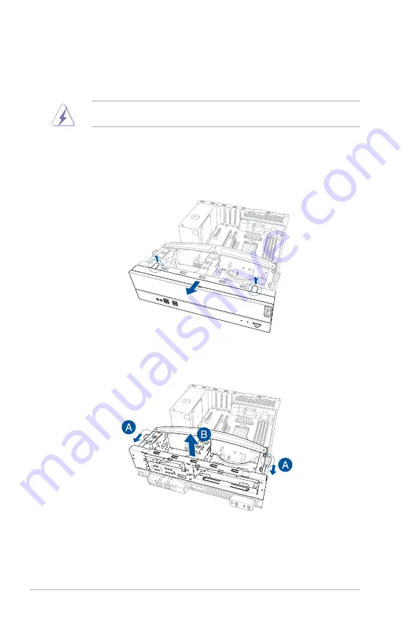
To remove the assembly module:
1.
Locate the front panel cover latches and lift both latches gently to remove the front
panel cover.
2.
Pull the assembly module lock towards the front (A) to release the assembly module
from the chassis, then lift the assembly module to remove it (B).
Summary of Contents for E500 G5 SFF
Page 1: ...Workstation E500 G5 SFF User Guide ...
Page 10: ...x ...
Page 27: ...2 9 ASUS E500 G5 SFF To remove a DIMM 2 5 1 DIMM installation ...
Page 48: ...Chapter 2 Hardware Setup 2 30 ...
Page 72: ...Chapter 3 Motherboard Information 3 24 ...
Page 118: ...4 46 Chapter 4 BIOS Setup ...
Page 133: ...A Appendix Appendix ...


