Chapter 3: Motherboard Information
3-22
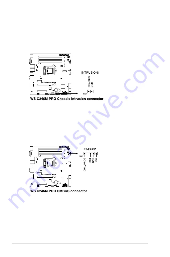
16. Chassis Intrusion (2-pin INTRUSION1)
These leads are for the intrusion detection feature for chassis with intrusion sensor
or microswitch. When you remove any chassis component, the sensor triggers and
sends a high level signal to these leads to record a chassis intrusion event. The default
setting is to short the CHASSIS# and the GND pin by a jumper cap to disable the
function.
17. System Management Bus (SMBUS) connector (5-1 pin SMBUS1)
This connector controls the system and power management-related tasks. This
connector processes the messages to and from devices rather than tripping the
individual control lines.
Summary of Contents for E500 G5 SFF
Page 1: ...Workstation E500 G5 SFF User Guide ...
Page 10: ...x ...
Page 27: ...2 9 ASUS E500 G5 SFF To remove a DIMM 2 5 1 DIMM installation ...
Page 48: ...Chapter 2 Hardware Setup 2 30 ...
Page 72: ...Chapter 3 Motherboard Information 3 24 ...
Page 118: ...4 46 Chapter 4 BIOS Setup ...
Page 133: ...A Appendix Appendix ...


