background image

Chapter 2:  Hardware Setup

2-24

2.10 

BIOS update utility

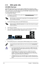
USB BIOS Flashback

USB BIOS Flashback allows you to easily update the BIOS without entering the existing 

BIOS or operating system. Simply insert a USB storage device to the USB port (the USB port 

hole marked in green on the I/O shield) then press the USB BIOS Flashback button for three 

seconds to automatically update the BIOS.

To use USB BIOS Flashback:

1.   Download the latest BIOS from the support site at http://support.asus.com and save it 

to as USB storage device.

We recommend you to use a USB 2.0 storage device to save the latest BIOS version for 

better compatibility and stability.

2. 

Insert the USB storage device to the USB Flashback port.

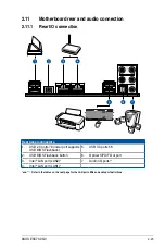
Refer to section 

2.11.1 Rear I/O connection

 for the location of the USB port that supports 

USB BIOS Flashback.

3. 

Shut down your computer.

4. 

Press the BIOS Flashback button for three seconds until the Flashback LED blinks 

three times, indicating that the BIOS Flashback function is working.

• 

Do not unplug portable disk, power system, or press the CLR_CMOS button while 

BIOS update is ongoing, otherwise update will be interrupted. In case of interruption, 

please follow the steps again.

• 

If the light flashes for five seconds and turns into a solid light, this means that 

the BIOS Flashback is not operating properly. This may be caused by improper 

installation of the USB storage device and filename/file format error. If this scenario 

happens, please restart the system to turn off the light.

• 

Updating BIOS may have risks. If the BIOS program is damaged during the process 

and results to the system’s failure to boot up, please contact your local ASUS Service 

Center.

For more BIOS update utilities in BIOS setup, refer to the section 

4.11 Updating BIOS

 in 

Chapter 4.

BIOS Flashback button

USB BIOS Flashback port

5. 

Wait until the light goes out, indicating that the BIOS updating process is completed.

Summary of Contents for ESC700

Page 1: ...Workstation ESC700 G3 User Guide ...

Page 2: ...ption of business and the like even if ASUS has been advised of the possibility of such damages arising from any defect or error in this manual or product Specifications and information contained in this manual are furnished for informational use only and are subject to change at any time without notice and should not be construed as a commitment by ASUS ASUS assumes no responsibility or liability...

Page 3: ... panel LEDs 1 8 1 7 2 Rear panel LEDs 1 8 Chapter 2 Hardware Setup 2 1 Chassis cover 2 2 2 1 1 Removing the side cover 2 2 2 2 CPU installation 2 4 2 3 CPU heatsink and fan assembly installation 2 7 2 4 System memory 2 8 2 4 1 Installing a DIMM on a single clip DIMM socket 2 10 2 5 Front panel cover 2 11 2 5 1 Removing the front panel cover 2 11 2 6 5 25 inch drives 2 12 2 7 Hard disk drives HDD 2...

Page 4: ... Configuration 4 34 4 6 3 PCH Storage Configuration 4 35 4 6 4 System Agent Configuration 4 37 4 6 5 USB Configuration 4 39 4 6 6 Platform Misc Configuration 4 41 4 6 7 Onboard Devices Configuration 4 42 4 6 8 APM Configuration 4 44 4 6 9 Network Stack Configuration 4 45 4 6 10 NVMe Configuration 4 45 4 7 Monitor menu 4 46 4 8 Boot menu 4 48 4 9 Tool menu 4 54 4 9 1 ASUS EZ Flash 2 Utility 4 54 4 ...

Page 5: ...ting a RAID driver disk without entering the OS 5 8 5 2 2 Creating a RAID driver disk in Windows 5 9 5 2 3 Installing the RAID driver during Windows OS installation 5 9 Chapter 6 Driver Installation 6 1 Installing an operating system 6 2 6 2 Support DVD information 6 2 6 2 1 Running the support DVD 6 2 6 2 2 Obtaining the software manuals 6 4 6 3 Software information 6 5 6 4 ASUS Utilities 6 5 6 4...

Page 6: ... harmful interference to radio or television reception which can be determined by turning the equipment off and on the user is encouraged to try to correct the interference by one or more of the following measures Reorient or relocate the receiving antenna Increase the separation between the equipment and receiver Connect the equipment to an outlet on a circuit different from that to which the rec...

Page 7: ...ur commitment to the highest standards for protecting our environment We believe in providing solutions for you to be able to responsibly recycle our products batteries other components as well as the packaging materials Please go to http csr asus com english Takeback htm for detailed recycling information in different regions Australia statement notice From 1 January 2012 updated warranties apply...

Page 8: ...efore operating the server carefully read all the manuals included with the server package Before using the server make sure all cables are correctly connected and the power cables are not damaged If any damage is detected contact your dealer as soon as possible To avoid short circuits keep paper clips screws and staples away from connectors slots sockets and circuitry Avoid dust humidity and temp...

Page 9: ...res that you have to perform when installing or removing system components 3 Chapter 3 Motherboard Information This chapter includes the motherboard layout and brief descriptions of the jumpers and internal connectors 4 Chapter 4 BIOS Setup This chapter tells how to change system settings through the BIOS Setup menus and describes the BIOS parameters 5 Chapter 5 RAID Configuration This chapter pro...

Page 10: ...ing to complete a task CAUTION Information to prevent damage to the components when trying to complete a task IMPORTANT Instructions that you MUST follow to complete a task NOTE Tips and additional information to help you complete a task Typography Bold text Indicates a menu or an item to select Italics Used to emphasize a word or a phrase Key Keys enclosed in the less than and greater than sign m...

Page 11: ...This chapter describes the general features of the server including sections on front panel and rear panel specifications 1 Product Introduction Chapter 1 Product Introduction ...

Page 12: ...SUS Technical Support team you must take note of the product s serial number containing 12 characters such as xxS0xxxxxxxx shown as the figure below With the correct serial number of the product ASUS Technical Support team members can then offer a quicker and satisfying solution to your problems Model Name ESC700 G3 Accessories 1 x ESC700 G3 Support CD 1 x AC Power Cable Optional Items DVD ROM DVD...

Page 13: ...PU Storage Intel X99 Express Chipset with RAID 0 1 5 10 and Intel Rapid Storage Technology 13 support 8 x SATA 6 0 Gb s ports 4 x right angle connectors from controller 1 4 x vertical connectors from controller 2 1 x SATA Express port gray at bottom compatible with 2 x SATA 6 0 Gb s ports 1 x M 2 Socket 3 with M Key 2260 2280 storage devices support SATA PCIE mode M 2 Socket shares bandwidth with ...

Page 14: ...ector 1 x MemOK button 1 x Clear CMOS button 1 x 3 pin Chassis intrusion CHASSIS connector 1 x DRCT DirectKey connector 1 x TPU switch advanced two stage adjustments 1 x EPU switch 1 x EZ XMP switch 1 x Power on button 1 x Reset button 1 x System Panel 1 x SMBus headers Dimension HH x WW x DD 423 mm x 190 mm x 435 mm Net Weight Kg CPU DRAM HDD excluded 11 Kg Power Supply 700W 80Plus Single Power S...

Page 15: ...uttons LED indicators optical drive and USB ports are all conveniently located at the front panel for easy access Refer to the Front panel LEDs section for the LED descriptions Optical Drive Optional Empty 5 25 inch bay HDD access LED Reset button Microphone port Headphone port Power button USB 2 0 ports USB 3 0 ports Power LED Card readers ...

Page 16: ...erboard rear I O ports expansion slots a vent for the system fan and the power supply module 700W Gold Single power supply Power connector Expansion slots PCI E latch USB 2 0 ports Gigabit LAN port 1 120 mm x 120 mm system fan vents Gigabit LAN port 2 USB 3 0 ports USB BIOS flashback button Audio ports ...

Page 17: ...e USB ports on the front or rear panel WARNING HAZARDOUS MOVING PARTS KEEP FINGERS AND OTHER BODY PARTS AWAY Turn off the system power and detach the power supply before removing or replacing any system component 1 Power supply unit 2 120 mm x 120 mm system fan 3 ASUS X99 WS SYS Server Board 4 Expansion card locks 5 Optical drive Optional 6 1 x 5 25 inch drive bay 7 Front I O board hidden 8 3 x 3 ...

Page 18: ...em power ON HDD Access LED OFF Blinking No activity Read write data into the HDD HDD Access LED Power LED 1 7 2 Rear panel LEDs ACT LINK LED SPEED LED Status Description Status Description OFF No link OFF 10 Mbps connection GREEN Linked ORANGE 100 Mbps connection BLINKING Data activity GREEN 1 Gbps connection SPEED LED ACT LINK LED ...

Page 19: ... Setup This chapter lists the hardware setup procedures that you have to perform when installing system components It includes description of the jumpers and connectors on the motherboard Chapter 2 Hardware Setup ...

Page 20: ...our fingers from components inside the chassis that can cause injury such as the CPU fan rear fan and other sharp edged parts The images of the barebone server shown in this section are for reference purposes only and may not exactly match the model you purchase To remove the side cover 1 Remove the two screws that secure the side cover 2 Press the side cover locks outward Side cover locks Screws ...

Page 21: ...2 3 ASUS ESC700 G3 3 Slightly pull the side cover toward the rear just enough to detach it from the chassis 4 Remove the cover and set it aside ...

Page 22: ...ny damage to the PnP cap socket contacts motherboard components ASUS will shoulder the cost of repair only if the damage is shipment transit related Keep the cap after installing the motherboard ASUS will process Return Merchandise Authorization RMA requests only if the motherboard comes with the cap on the LGA2011 v3 socket The product warranty does not cover damage to the socket contacts resulti...

Page 23: ...2 5 ASUS ESC700 G3 A B B C A B A Triangle mark Triangle mark ...

Page 24: ...Chapter 2 Hardware Setup 2 6 A B A C B Apply the Thermal Interface Material to the CPU heatsink and CPU before you install the heatsink and fan if necessary ...

Page 25: ...2 7 ASUS ESC700 G3 2 3 CPU heatsink and fan assembly installation To install the CPU heatsink and fan assembly ...

Page 26: ...urations 2 4 System memory The motherboard comes with eight DDR 4 Double Data Rate 4 Quad Inline Memory Modules DIMM slots A DDR4 module is notched differently from a DDR DDR2 or DDR3 module DO NOT install a DDR DDR2 or DDR3 memory module to the DDR4 slot ...

Page 27: ...nder the default state some memory modules for overclocking may operate at a lower frequency than the vendor marked value To operate at the vendor marked or at a higher frequency refer to section 4 5 Ai Tweaker menu for manual memory frequency adjustment For system stability use a more efficient memory cooling system to support a full memory load 8 DIMMs or overclocking condition Memory modules wi...

Page 28: ...the socket Unlocked retaining clip DIMM notch DIMM slot key 1 Press the retaining clip outward to unlock the DIMM 2 Remove the DIMM from the socket Removing a DIMM from a single clip DIMM socket To install two or more DIMMs refer to the user guide bundled in the motherboard package Refer to the user guide for qualified vendor lists of the memory modules Support the DIMM lightly with your fingers w...

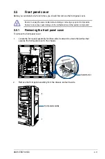
Page 29: ...tem components Failure to do so may cause damage to the motherboard and other system components 2 5 1 Removing the front panel cover To remove the front panel cover 1 Locate the front panel assembly lock then slide it outward to unlock the latches that secures the front panel cover to the chassis 2 Remove the front panel assembly from the chassis and set it aside Assembly lock Front panel assembly...

Page 30: ...ay you intend to use Take extra care when removing the metal cover Use tools such as a screw driver to bend and remove the metal cover to avoid physical injury This system comes with three 5 25 inch drive bays located on the upper front section of the chassis If your system came with an optical drive the optical drive occupies the topmost bay 1 The lower bays 2 and 3 are available for additional 5...

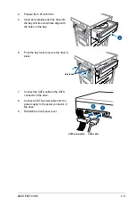
Page 31: ...om the power supply to the power connector of the drive 9 Reinstall the front panel cover 4 Prepare the 5 25 inch drive 5 Insert and carefully push the drive into the bay until its screw holes align with the holes on the bay 6 Push the bay locks to secure the drive in place Bay locks SATA cable SATA power cable ...

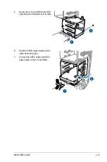
Page 32: ...rd disk drives 1 Remove the side cover of the chassis Refer to the Removing the side cover section for more information 2 Prepare the 3 5 inch HDD and the bundled set of screws 3 Locate the HDD cage lock press the it up A then swing the HDD cage outwards B until it clicks in place 4 Align and insert the 3 5 inch HDD into the drive bay ensuring that the screw holes on the HDD matches the screw hole...

Page 33: ... ESC700 G3 5 Secure the 3 5 inch HDD to the HDD cage using the bundled set of screws 6 Swing the HDD cage inwards until it clicks back into place 7 Connect the SATA cable and SATA power cable to the 3 5 inch HDD ...

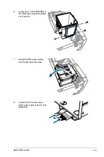
Page 34: ...epare the 2 5 inch HDD SDD and the bundled set of screws 3 Lay the system on its side on a flat and stable surface 4 Locate the HDD cage lock press it up A then swing the HDD cage outwards B 5 Align and insert the 2 5 inch HDD SSD into the drive bay as shown Push it all the way until its screw holes align with the holes on the drive bay HDD cage lock HDD cage Matching screw holes 2 5 inch HDD SSD ...

Page 35: ...700 G3 6 Secure the 2 5 inch HDD SSD to the HDD cage using the bundled set of screws 7 Swing the HDD cage inwards until it clicks back into place 8 Connect a SATA cable and a SATA power cable to the 2 5 inch HDD SSD ...

Page 36: ...age motherboard components Slot No Slot Description 40 LANE 28 LANE 1 PCIe 3 0 2 0 x16_1 slot PCIe 3 0 2 0 x16_1 slot 2 PCIe 3 0 2 0 x16_2 slot PCIe 3 0 2 0 x16_2 slot 3 PCIe 3 0 2 0 x16_3 slot PCIe 3 0 2 0 x16_3 slot 4 PCIe 3 0 2 0 x16_4 slot PCIe 3 0 2 0 x16_4 slot 5 PCIe 3 0 2 0 x16_5 slot PCIe 3 0 2 0 x16_5 slot This slot may not work if a 28 LANE CPU is installed ...

Page 37: ...1 Lay the system on its side on a flat stable surface 2 Press the PCI E latch A hold it by its edge then lift it towards the rear B 3 Remove the screw A that secures the metal bracket to the chassis then remove the metal bracket B Metal bracket PCI E latch Edge of the PCI E latch Screw ...

Page 38: ... and insert the expansion card into the PCI E slot 5 Lift the PCI E latch inwards until it clicks into place securing the expansion card to the chassis 6 Optional Replace the screw of the metal bracket PCI E slot Expansion card PCI E latch ...

Page 39: ... PCIe 3 0 2 0 x16_4 PCIe 3 0 2 0 x16_5 Single VGA PCIe card N A x16 N A N A N A Dual VGA PCIe cards N A x16 x16 N A N A Triple VGA PCIe cards N A x16 x16 N A x8 Quintuple VGA PCIe cards x8 x8 x8 x8 x8 28 LANE CPU PCI Express 3 0 operating mode VGA configuration PCIe 3 0 2 0 x16_1 PCIe 3 0 2 0 x16_2 PCIe 3 0 2 0 x16_3 PCIe 3 0 2 0 x16_4 PCIe 3 0 2 0 x16_5 Single VGA PCIe card N A x16 N A N A N A Du...

Page 40: ...16_3 shared PCIe x16_4 shared PCIe x16_5 shared SMBUS Controller shared Intel SATA Controller 1 shared Intel SATA Controller 2 shared Intel LAN1 i210 shared Intel LAN2 i210 shared Intel xHCI shared Intel EHCI 1 shared Intel EHCI 2 shared HD Audio shared IRQ assignments for this motherboard ...

Page 41: ...ced because it was damaged or became defective To remove the system fan 1 Disconnect the system fan cable from the REAR_FAN1 connector on the motherboard 3 Remove the system fan 2 Remove the four system fan screws at the rear panel Keep the screws for later use Hold the system fan with one hand while removing the system fan screws Follow the previous instructions in reverse order if you want to re...

Page 42: ...s the BIOS Flashback button for three seconds until the Flashback LED blinks three times indicating that the BIOS Flashback function is working Do not unplug portable disk power system or press the CLR_CMOS button while BIOS update is ongoing otherwise update will be interrupted In case of interruption please follow the steps again If the light flashes for five seconds and turns into a solid light...

Page 43: ...fer to the tables on the next page for the LAN port LEDs and audio port definitions Rear panel connectors 1 USB 2 0 ports 78 lower port supports USB BIOS Flashback 5 USB 3 0 ports 56 2 USB BIOS Flashback button 6 Optical S PDIF Out port 3 Intel LAN port LAN2 7 Audio I O ports 4 Intel LAN port LAN1 ...

Page 44: ...ations ACT LINK LED SPEED LED LAN port Activity Link LED Speed LED Status Description Status Description Off No link Off 10 Mbps connection Orange Linked Orange 100 Mbps connection Orange Blinking Data activity Green 1 Gbps connection Orange Blinking then steady Ready to wake up from S5 mode You can disable the LAN controllers in BIOS Due to hardware design the LAN1 port s LEDs may continue to bli...

Page 45: ...2 27 ASUS ESC700 G3 Connect to Headphone and Mic Connect to Stereo Speakers 2 11 2 Audio I O connection Audio I O ports ...

Page 46: ...Chapter 2 Hardware Setup 2 28 Connect to 4 1 channel Speakers Connect to 5 1 channel Speakers Connect to 2 1 channel Speakers ...

Page 47: ...2 29 ASUS ESC700 G3 When the DTS UltraPC II function is enabled ensure to connect the rear speaker to the light blue port Connect to 7 1 channel Speakers ...

Page 48: ...Chapter 2 Hardware Setup 2 30 ...

Page 49: ...This chapter includes the motherboard layout and brief descriptions of the jumpers and internal connectors 3 Motherboard Information Chapter 3 Motherboard Information ...

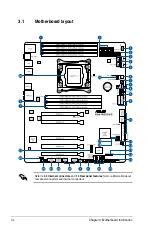
Page 50: ...Chapter 3 Motherboard Information 3 2 Refer to 3 5 Internal connectors and 1 5 Rear panel features for more information about rear panel connectors and internal connectors 3 1 Motherboard layout ...

Page 51: ...rusion connector 4 1 pin CHASSIS 3 27 12 Clear CMOS button CLR_CMOS 3 8 13 System Management Bus SMBUS connector 5 1 pin SMBUS1 3 18 14 DirectKey connector 2 pin DRCT 3 25 15 T_Sensor connector 2 pin T_SENSOR1 3 26 16 MemOK button 3 5 17 Chassis Fan control setting jumper 3 pin CHAFAN_SEL 3 9 18 CPU Over Voltage jumper 3 pin CPU_OV 3 9 19 System panel connector 20 1 pin PANEL 3 24 20 Serial ATA 3 ...

Page 52: ...tinually change settings to enhance system performance 1 Power on button The motherboard comes with a power on button that allows you to power up or wake up the system The button also lights up when the system is plugged to a power source indicating that you should shut down the system and unplug the power cable before removing or installing any motherboard component 2 Reset button Press the reset...

Page 53: ...he next set of failsafe settings The blinking speed of the DIAG_DRAM LED increases indicating different test processes Due to memory tuning requirement the system automatically reboots when each timing set is tested If the installed DIMMs still fail to boot after the whole tuning process the DIAG_DRAM LED lights continuously Replace the DIMMs with ones recommended in the Memory QVL Qualified Vendo...

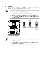
Page 54: ...ally adjusts the CPU ratio for an enhanced performance When the TPU switch is set to Enabled TPU_II CPU BCLK and Ratio Boost the system automatically adjusts the base clock rate BCLK and the CPU ratio for a more enhanced performance The TPU LEDs TPU_LED near the TPU switch light up when you set the TPU switch to TPU_I mode or TPU_II mode Refer to section 3 4 Onboard LEDs for the exact location of ...

Page 55: ...LED3 near the EPU switch lights up when you enable the EPU switch Refer to section 3 4 Onboard LEDs for the exact location of the EPU LED If you enable this switch under Windows OS environment the EPU function will be activated after the next system bootup You may change the EPU settings in BIOS setup program and enable the EPU function at the same time However the system will use the last setting...

Page 56: ...rmation only when the systems hangs due to overclocking 7 EZ XMP switch Enable this switch to overclock the installed DIMMs allowing you to enhance the DIMM s speed and performance The EZ XMP LED XLED1 lights up when you enable the EZ XMP switch For the location of the EZ XMP LED refer to section 3 4 Onboard LEDs ...

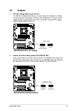
Page 57: ...e CPU voltage setting insert the jumper to pins 2 3 To go back to its default CPU voltage setting insert the jumper to pins 1 2 2 Chassis Fan control setting jumper 3 pin CHAFAN_SEL These jumpers allow you to switch fan pin selection The CHAFAN_SEL jumper is for the front fans and rear fans control Set pins 1 2 to let the BIOS control the settings of the chassis fans Set pins 2 3 to control the se...

Page 58: ...CPU The Diagnosis LEDs provide the status of these key components during POST Power On Self Test CPU memory modules VGA card and hard disk drives If an error is found the critical component s LED stays lit up until the problem is solved 2 TPU LED TPU_LED The TPU LED lights up when the TPU switch is enabled ...

Page 59: ...ASUS ESC700 G3 3 11 3 EPU LED O2LED3 The EPU LED lights up when the EPU switch is enabled 4 EZ XMP LED XLED1 This LED lights up when you enable the EZ XMP switch ...

Page 60: ...Chapter 3 Motherboard Information 3 12 5 Q Code LEDs The Q Code LED design provides you with a 2 digit error code that displays the system status Refer to the Q Code table on the next page for details ...

Page 61: ...lization error 55 Memory not installed 56 Invalid CPU type or Speed 57 CPU mismatch 58 CPU self test failed or possible CPU cache error 59 CPU micro code is not found or micro code update is failed 5A Internal CPU error 5B Reset PPI is not available 5C 5F Reserved for future AMI error codes E0 S3 Resume is stared S3 Resume PPI is called by the DXE IPL E1 S3 Boot Script execution E2 Video repost E3...

Page 62: ...le initialization 79 CSM initialization 7A 7F Reserved for future AMI DXE codes 90 Boot Device Selection BDS phase is started 91 Driver connecting is started 92 PCI Bus initialization is started 93 PCI Bus Hot Plug Controller Initialization 94 PCI Bus Enumeration 95 PCI Bus Request Resources 96 PCI Bus Assign Resources 97 Console Output devices connect 98 Console input devices connect 99 Super IO ...

Page 63: ...e not available D4 PCI resource allocation error Out of Resources D5 No Space for Legacy Option ROM D6 No Console Output Devices are found D7 No Console Input Devices are found D8 Invalid password D9 Error loading Boot Option LoadImage returned error DA Boot Option is failed StartImage returned error DB Flash update is failed DC Reset protocol is not available ACPI ASL Checkpoints under OS Code De...

Page 64: ...f these connectors then install the module to a slot opening at the back of the system chassis 2 Digital audio connector 4 1 pin SPDIF_OUT This connector is for an additional Sony Philips Digital Interface S PDIF port Connect the S PDIF Out module cable to this connector then install the module to a slot opening at the back of the system chassis The S PDIF module is purchased separately ...

Page 65: ... onboard Intel X99 chipset These connectors are set to AHCI Mode by default If you intend to create a Serial ATA RAID set using these connectors set the SATA Mode item in the BIOS to RAID Mode Refer to section 4 6 3 PCH Storage Configuration for details Before creating a RAID set refer to the manual bundled in the motherboard support DVD The SATAEXPRESS_1 connector can support one SATA Express dev...

Page 66: ...ves you can use a software RAID solution to create a RAID 0 RAID 1 RAID 5 or a RAID 10 configuration For more information on the SATA RAID solutions supported on this motherboard refer to the RAID Configuration chapter of this user guide 5 System Management Bus SMBUS connector 5 1 pin SMBUS1 This connector controls the system and power management related tasks This connector processes the messages...

Page 67: ... Connect one end of the front panel audio I O module cable to this connector We recommend that you connect a high definition front panel audio module to this connector to avail of the motherboard s high definition audio capability If you want to connect a high definition or an AC 97 front panel audio module to this connector set the Front Panel Type item in the BIOS setup to HD Audio or AC97 ...

Page 68: ... speeds of up to 5 Gb s faster charging time for USB chargeable devices optimized power efficiency and backward compatibility with USB 2 0 The USB 3 0 module is purchased separately Ensure to install the related driver to fully use the USB 3 0 ports under Windows 7 The plugged USB 3 0 device may run on xHCI or EHCI mode depending on the operating system s setting These USB 3 0 ports support native...

Page 69: ... USB connector onboard if your chassis supports front panel USB ports The USB 2 0 module is purchased separately 8 USB 2 0 connectors 10 1 pin USB910 US1112 These connectors are for USB 2 0 ports Connect the USB module cable to any of these connectors then install the module to a slot opening at the back of the system chassis These USB connectors comply with USB 2 0 specification that supports up ...

Page 70: ...e of each cable matches the ground pin of the connector The CPU_FAN1 2 connectors support the CPU fan of maximum 1A 12 W fan power DO NOT forget to connect the fan cables to the fan connectors Insufficient air flow inside the system may damage the motherboard components These are not jumpers Do not place jumper caps on the fan connectors Ensure that the CPU fan cable is securely installed to the C...

Page 71: ...r is inadequate If you want to use two or more high end PCI Express x16 cards use a PSU with 1000W power or above to ensure the system stability If you are uncertain about the minimum power supply requirement for your system refer to the Recommended Power Supply Wattage Calculator at http support asus com PowerSupplyCalculator PSCalculator aspx SLanguage en us for details 10 ATX power connectors 2...

Page 72: ...ing speaker 4 pin SPEAKER This 4 pin connector is for the chassis mounted system warning speaker The speaker allows you to hear system beeps and warnings ATX power button soft off button 2 pin PWRSW This connector is for the system power button Pressing the power button turns the system on or puts the system in sleep or soft off mode depending on the operating system settings Pressing the power sw...

Page 73: ...ensures platform integrity 13 DirectKey connector 2 pin DRCT This connector is for the chassis mounted button that supports the DirectKey function Connect the button cable that supports DirectKey from the chassis to this connector on the motherboard Ensure that your chassis comes with the extra button cable that supports the DirectKey feature Refer to the technical documentation that came with the...

Page 74: ... supports M Key and type 2260 2280 storage devices This socket supports PCIe and SATA modes 15 T_Sensor connector 2 pin T_SENSOR1 This connector is for the thermistor cable that allows you to monitor the temperature of your motherboard s critical components and connected devices The thermistor cable is purchased separately ...

Page 75: ...his connector when a chassis component is removed or replaced The signal is then generated as a chassis intrusion event By default the pin labeled Chassis Signal and Ground are shorted with a jumper cap Remove the jumper caps and enable the related options in BIOS if you intend to use the chassis intrusion detection feature A message appears when you connect the sensor or switch at the first time ...

Page 76: ...Chapter 3 Motherboard Information 3 28 ...

Page 77: ...4 BIOS Setup This chapter tells how to change the system settings through the BIOS Setup menus Detailed descriptions of the BIOS parameters are also provided Chapter 4 BIOS Setup ...

Page 78: ...advanced power management and boot device configuration that are needed for system startup in the motherboard CMOS In normal circumstances the default BIOS settings apply to most conditions to ensure optimal performance DO NOT change the default BIOS settings except in the following circumstances An error message appears on the screen during the system bootup and requests you to run the BIOS Setup...

Page 79: ...oard buttons and switches for information on how to erase the RTC RAM via the Clear CMOS button The BIOS setup program does not support Bluetooth devices 4 2 BIOS setup program Use the BIOS Setup to update the BIOS or configure its parameters The BIOS screen include navigation keys and brief onscreen help to guide you in using the BIOS Setup program Entering BIOS at startup To enter BIOS Setup at ...

Page 80: ...gure below shows an example of the Advanced Mode Refer to the following sections for the detailed configurations Configuration fields Menu bar Item description Sub menu item Menu items Scroll bar Language EZ Tuning Wizard MyFavorite Quick Note Hot Keys Shows the last modified items Displays the CPU motherboard temperature CPU and memory voltage output ...

Page 81: ...ems My Favorites Ai Tweaker Advanced Monitor Boot Tool and Exit on the menu bar have their respective menu items Submenu items A greater than sign before each item on any menu screen means that the item has a submenu To display the submenu select the item and press Enter Language This button above the menu bar contains the languages that you can select for your BIOS Click this button to select the...

Page 82: ...e items that do not fit on the screen Press the Up Down arrow keys or Page Up Page Down keys to display the other items on the screen General help At the top right corner of the menu screen is a brief description of the selected item Use F12 key to capture the BIOS screen and save it to the removable storage device Configuration fields These fields show the values for the menu items If an item is ...

Page 83: ...ess F11 on your keyboard or click from the BIOS screen to open EZ Tuning Wizard screen then click Next 2 Select a PC scenario Daily Computing or Gaming Media Editing then click Next 3 Select the CPU fan type Box cooler Tower cooler or Water cooler that you installed then click Next If you are not sure of the CPU fan type click I m not sure The system automatically detects the CPU fan type 4 Click ...

Page 84: ... type of storage for your RAID Easy Backup or Super Speed then click Next a For Easy Backup click Next then select from Easy Backup RAID1 or Easy Backup RAID10 4 After selecting the type of RAID click Next then click Yes to continue the RAID setup 5 After the RAID setup is done click Yes to exit the setup then click OK to reset your system You can only select Easy Backup RAID 10 if you connect fou...

Page 85: ...ASUS ESC700 G3 4 9 4 3 My Favorites MyFavorites is your personal space where you can easily save and access your favorite BIOS items ...

Page 86: ...click the submenu that you want to save as favorite from the submenu panel and tap or click or press Enter on your keyboard You cannot add the following items to My Favorite items Items with submenu options User managed items such as language and boot order Configuration items such as Memory SPD Information system time and date 4 Click Exit ESC or press esc key to close Setup Tree Map screen 5 Go ...

Page 87: ... settings Security The Security menu items allow you to change the system security settings If you have forgotten your BIOS password erase the CMOS Real Time Clock RTC RAM to clear the BIOS password See section 3 2 Onboard buttons and switches for information on how to erase the RTC RAM via the Clear CMOS button The Administrator or User Password items on top of the screen show the default Not Ins...

Page 88: ...er when prompted to create confirm the password After you clear the password the Administrator Password item on top of the screen shows Not Installed User Password If you have set a user password you must enter the user password for accessing the system The User Password item on top of the screen shows the default Not Installed After you set a password this item shows Installed To set a user passw...

Page 89: ...Ai Overclock Tuner Auto This item allows you to select the CPU overclocking options to achieve the desired CPU internal frequency Select any of these preset overclocking configuration options Auto Loads the optimal settings for the system Manual Automatically optimizes the CPU ratio and BCLK frequency The following item appears only when you set the Ai Overclocking Tuner to Manual CPU Strap Auto T...

Page 90: ...ce Use the or keys to adjust the value The values range from 80 0 MHz to 300 0 MHz We recommend you to set the value based on the CPU specification as high BCLK frequencies may damage the CPU permanently Initial BCLK Frequency Auto This item allows you to start overclocking the system from the initial BCLK base clock frequency to the assigned BCLK frequency Use the or keys to adjust the value The ...

Page 91: ...e Ratio Limit 2 Core Ratio Limit and 3 Core Ratio to Auto 5 Core Ratio Limit Auto Select Auto to apply the CPU default Turbo Ratio setting or manually assign a 5 Core Limit value that must be higher than or equal to the 6 Core Ratio Limit If you assign a value for 5 Core Ratio Limit do not set the 1 Core Ratio Limit 2 Core Ratio Limit 3 Core Ratio and 4 Core Ratio to Auto 6 Core Ratio Limit Auto S...

Page 92: ...3600MHz DDR4 3733MHz DDR4 3800MHz DDR4 4000MHz OC Tuner Keep Current Settings This item allows you to automatically overclock the CPU and DRAM frequencies and voltage for an enhanced system performance It also accelerates the CPU graphics performance to the extreme depending on the CPU graphics loading Configuration options Keep Current Settings Ratio Tuning BCLK Ratio Tuning Ensure that you insta...

Page 93: ...RAM RAS to RAS Delay L Auto Configuration options Auto 1 7 DRAM REF Cycle Time Auto Configuration options Auto 1 1023 DRAM Refresh Interval Auto Configuration options Auto 1 32767 DRAM WRITE Recovery Time Auto Configuration options Auto 1 31 DRAM READ to PRE Time Auto Configuration options Auto 1 15 DRAM FOUR ACT WIN Time Auto Configuration options Auto 1 63 DRAM WRITE to READ Delay Auto Configura...

Page 94: ...Auto 1 7 tRWSR Auto Configuration options Auto 1 7 tCCD Auto Configuration options Auto 1 7 tUWRDR Auto Configuration options Auto 1 3 tRWDR2 Auto Configuration options Auto 0 31 tRWDD Auto Configuration options Auto 0 31 tRWSR2 Auto Configuration options Auto 0 31 tWRDD2 Auto Configuration options Auto 0 31 tCCDWR Auto Configuration options Auto 0 7 tCCD_L Auto Configuration options Auto 1 3 RTL ...

Page 95: ...TL CHC D1 R0 Auto Configuration options Auto 1 127 DRAM RTL CHC D1 R1 Auto Configuration options Auto 1 127 DRAM RTL CHD D0 R0 Auto Configuration options Auto 1 127 DRAM RTL CHD D0 R1 Auto Configuration options Auto 1 127 DRAM RTL CHD D1 R0 Auto Configuration options Auto 1 127 DRAM RTL CHD D1 R1 Auto Configuration options Auto 1 127 DRAM IO L CHA D0 R0 Auto Configuration options Auto 1 255 DRAM I...

Page 96: ...55 DRAM IO L CHD D1 R1 Auto Configuration options Auto 1 255 IO control MC Vref CHA Auto Configuration options Auto 50 99 911 MC Vref CHB Auto Configuration options Auto 50 99 911 MC Vref CHC Auto Configuration options Auto 50 99 911 MC Vref CHD Auto Configuration options Auto 50 99 911 DRAM Vref CHA Auto Configuration options Auto 60 99 DRAM Vref CHB Auto Configuration options Auto 60 99 DRAM Vre...

Page 97: ...to Configuration options Auto 0 80 1 60 Transmitter CMD De emphasis Auto Configuration options Auto 0 80 1 60 Receiver CLK Pre emphasis Auto Configuration options Auto 1 00 2 00 Receiver CLK De emphasis Auto Configuration options Auto 1 00 2 00 Transmitter CLK Pre emphasis Auto Configuration options Auto 1 00 2 00 Receiver CTL Pre emphasis Auto Configuration options Auto 1 00 1 60 Receiver CTL De ...

Page 98: ...ence code to be skipped when possible to increase boot speed Configuration options Auto Enabled Disabled DRAM Training Auto This item allows the system to set the training channel status of the installed DRAMs Configuration options Auto Ignore Enabled DRAM SPD Write Disabled This item allows you to enable disable the DRAM SPD write for memory SMBus programming Configuration options Enabled Disable...

Page 99: ...values range from 300 KHz to 600 KHz with an interval of 50 KHz VRM Spread Spectrum Disabled This item allows to enhance the system stability Configuration options Disabled Enabled Active Frequency Mode Disabled This item allows to enhance the power saving condition of your system Configuration options Disabled Enabled CPU Power Phase Control Auto This item allows you to set the power phase contro...

Page 100: ...monitored DRAM AB CD Current Capability 100 This item adjusts the total power range for DRAM overclocking Set a higher value to provide a wider total power range and extends the overclocking frequency range simultaneously Configuration options 100 110 120 130 DRAM AB CD Switching Frequency Auto This item affects the overclocking range and system stability Set this item to Manual to manually set a ...

Page 101: ... allows you to maintain the time window for Turbo Ratio over TDP Thermal Design Power Use the or keys to adjust the value The values range from 1 to 127 in seconds Short Duration Package Power Limit Auto Also known as Power Limit 2 this item allows you to provide rapid protection when the package power exceeds the Power Limit 1 Use the or keys to adjust the value The values range from 1 W t0 4095 ...

Page 102: ...ng its PCIE controller and power control unit PCU Setting a high system agent voltage may enhance the overclocking capability Use the or key to adjust the value The values range from 0 001 V to 0 999 V at 0 001 V increment CPU Core Voltage Auto This item allows you to configure the amount of Voltage fed to the CPU cores Increase the voltage when configuring a high CPU core frequency Configuration ...

Page 103: ...CPU Cache Voltage Override Auto This item allows you to configure the CPU cache voltage Use or key to adjust the value The values range from 0 001 V to 1 920 V at 0 001 V increment The following items appear only when you set the CPU Core Voltage to Offset Mode Offset Mode Sign To offset the voltage by a positive value To offset the voltage by a negative value CPU Cache Voltage Offset Auto This it...

Page 104: ...HD Auto This item allows you to set the voltage for the system memory Use the or key to adjust the value The values range from 0 80 V to 1 90 V at 0 010 V increment According to Intel CPU specifications DIMMs with voltage requirement over 1 65 V may damage the CPU permanently We recommend that you install the DIMMs with the voltage requirement below 1 65 V PCH Core Voltage Auto This item allows yo...

Page 105: ...ltage You can use the or keys to adjust the value The values range from 0 20000 V to 3 098278 V with a 0 006602 V interval PLL Reference Offset Mode Sign To offset the voltage by a positive value To offset the voltage by a negative value PLL Reference Offset Value Auto This item allows you to configure the PLL reference value You can use the or keys to adjust the value Configuration options Auto 1...

Page 106: ...Advanced menu The Advanced menu items allow you to change the settings for the CPU and other system devices Be cautious when changing the settings of the Advanced menu items Incorrect field values can cause the system to malfunction ...

Page 107: ...reasing its frequency as it reaches the thermal throttle point The thermal monitor includes TM1 Thermal monitor 1 TM2 Thermal monitor 2 and EMTTM Enhanced Multi threaded Thermal Monitoring Configuration options Disabled Enabled Limit CPUID Maximum Disabled When set to Enabled this item allows the legacy OS to boot even without support for CPUs with extended CPUID functions Configuration options Di...

Page 108: ... a selected performance ratio based on CPU configuration Configuration options Max Efficient Turbo Performance Maximum CPU Core Temperature Auto This item allows you to set the maximum allowable temperature for CPU cores The CPU throttles or shuts down when it reaches its maximum temperature to prevent damaging the CPU cores Configuration options Auto 60 120 We recommend that you set the temperatu...

Page 109: ...ates to Enabled Enhanced C1 state Enabled This item allows your CPU to reduce power consumption when the system is in idle mode Configuration options Enabled Disabled CPU C3 Report Enabled This item allows you to disable or enable the CPU C3 report to the operating system Configuration options Enabled Disabled CPU C6 Report Enabled This item allows you to disable or enable the CPU C6 report to the...

Page 110: ...llows you to configure the PCI Express slots PCIe Speed Auto This item allows your system to automatically select the PCI Express port speed When set to Gen1 the PCI E port runs at PCI E 1 0 speed When set to Gen2 the PCI E port runs at PCI E 2 0 speed Configuration options Auto Gen1 Gen2 ...

Page 111: ...ions Enabled Disabled SATAExpress_1 SRIS Support Auto When set to Auto this item allows the system to automatically adjust the SRIS Separate Reference Clock Independent Spread Spectrum Clocking Architecture support for connected SATA Express devices Set this item to Disabled to activate ASUS RUNWAY SATA Express bridge card Configuration options Auto Disabled S M A R T Status Check On S M A R T Sel...

Page 112: ...ATA function IDE Mode Set to IDE Mode when you want to use the Serial ATA hard disk drives as Parallel ATA physical storage devices AHCI Mode Set to AHCI Mode when you want the SATA hard disk drives to use the AHCI Advanced Host Controller Interface The AHCI allows the onboard storage driver to enable advanced Serial ATA features that increases storage performance on random workloads by allowing t...

Page 113: ...peed of the PCIEX16_1 slot Configuration options Auto Gen1 Gen2 Gen3 PCIEX16_2 Link Speed Auto This item allows you to select the operating speed of the PCIEX16_2 slot Configuration options Auto Gen1 Gen2 Gen3 PCIEX16_3 Link Speed Auto This item allows you to select the operating speed of the PCIEX16_3 slot Configuration options Auto Gen1 Gen2 Gen3 PCIEX16_4 Link Speed Auto This item allows you to...

Page 114: ... enable disable the Intel Virtualization Technology for Directed I O VT d by reporting the I O device assignment to VMM via the DMAR ACPI Tables Configuration options Enabled Disabled MCTP Disabled This item allows you to enable disable Management Component Transport Protocol Configuration options Enabled Disabled ACS Control Disabled This item allows you to enable disable ACS Control Configuratio...

Page 115: ... system Smart Auto Upon detection the xHCI driver supports the USB 3 0 mode during both POST and operating system Enabled Enables the xHCI controller Disabled Disables the xHCI controller EHCI Legacy USB Support Enabled Enabled Your system supports the USB 2 0 devices in legacy operating systems Disabled Your USB 2 0 devices can be used for BIOS setup only and cannot be recognized in the boot devi...

Page 116: ...ables the xHCI Hand off support EHCI Hand off Disabled Enabled Enables the support for operating systems without an EHCI hand off feature Disabled Disables the EHCI Hand off support USB Single Port Control This item allows you to enable or disable the individual USB ports Refer to section 3 1 Motherboard layout for the location of the USB ports ...

Page 117: ...on options Auto Disabled L1 only PEG ASPM Support Disabled This item allows you to enable disable the ASPM support for the downstream devices Configuration options Disabled L1 only PCH PCI Express PCH DMI ASPM Disabled This item allows you to enable disable the PCH DMI ASPM Setting Configuration options Disabled Enabled ASPM Support Disabled This item allows you to enable disable the ASPM support ...

Page 118: ... the HD Audio Controller to Enabled Front Panel Type HD Audio This item allows you to set the front panel audio connector AAFP mode to legacy AC 97 or high definition audio depending on the audio standard that the front panel audio module supports HD Audio Sets the front panel audio connector AAFP mode to high definition audio AC97 Sets the front panel audio connector AAFP mode to legacy AC 97 SPD...

Page 119: ...ionRom of the Intel LAN controller Configuration options Enabled Disabled Serial Port Configuration The items in this menu allows you to set the parameters of the serial port This items in this menu works only if a serial port connector is installed on the motherboard Serial Port On This item allows you to enable disable the serial port Configuration options On Off Change Settings Auto This item a...

Page 120: ...he AC power loss Configuration options Power Off Power On Last State Power On By PCI E PCI Disabled This item allows you to enable disable the Wake on LAN function of the onboard LAN controller or other installed PCI E LAN cards Configuration options Disabled Enabled Power On By Ring Disabled This item allows you to enable disable the Power On by Ring feature of your motherboard Configuration opti...

Page 121: ...figuration options Disabled Enabled The following item appears only when you set the Network Stack to Enabled Ipv4 Ipv6 PXE Support Enabled This item allows you to enable disable the Ipv4 Ipv6 PXE wake event Configuration options Disabled Enabled 4 6 10 NVMe Configuration This item allows you to view the NVMe controller and drive information ...

Page 122: ...ures CPU FAN1 2 Speed xxxx RPM or Ignore N A REAR FAN1 Speed xxxx RPM or Ignore FRNT FAN1 3 Speed xxxx RPM or Ignore N A The onboard hardware monitor automatically detects and displays the CPU chassis and power fan speed in rotations per minute RPM If the fan is not connected to the motherboard the field shows N A Select Ignore if you do not wish to display the detected speed VCCIO VCORE1 VDDQ_AB ...

Page 123: ...duty cycle percentage to meet the thermal requirement for your system Use the or keys to adjust the value The values range from 0 to 100 with an interval of 5 CPU FAN 1 2 REAR FAN1 FRNT FAN1 FRNT FAN2 3 modes This item allows you to select a specific speed for your CPU and front fans Configuration options Generic Speed High Speed Full Speed Manual ...

Page 124: ...ices connected to SATA ports are available during POST This process extends the POST time Hard Drive Only Only hard drives connected to SATA ports are detected during POST Boot Drive Only Only boot drives connected to a SATA ports are detected during POST USB Support Partial Initialization Disabled All USB devices will not be available until OS boot up for a fastest POST time Full Initialization A...

Page 125: ...Setup You can only execute the POST delay time during normal boot The values range from 0 to 10 seconds This feature only works when set under normal boot The following items appear only when you set the Boot Logo Display to Disabled Post Report 5 sec This item allows you to select a desired POST report waiting time Configuration options 1 sec 10 sec Until Press ESC DirectKey DRCT Enabled Disabled...

Page 126: ...enable the CSM to fully support the non UEFI driver add on devices or the Windows UEFI mode Disabled Disables the CSM to fully support the non UEFI driver add on devices or the Windows UEFI mode The following items appear only when you set the Launch CSM to Enabled Boot Device Control UEFI and Legacy OpROM This item allows you to select the type of devices that you want to boot Configuration optio...

Page 127: ...atform key PK Key exchange Key KEK Signature database db and Revoked Signatures dbx When the default Secure boot keys are loaded the PK state will change from Unloaded mode to loaded mode Clear Secure Boot keys This item appears only when you load the default Secure Boot keys This item allows you to clear all default Secure Boot keys Save Secure Boot Keys This item allows you to save the PK Platfo...

Page 128: ...ture database lists the signers or images of UEFI applications operating system loaders and UEFI drivers that you can load on the single computer Delete the db This item allows you to delete the db file from your system Configuration options Yes No Load Default db This item allows you to load the downloaded db from a USB storage device Append Default db This item allows you to load the additional ...

Page 129: ...uence from the available devices The number of device items that appears on the screen depends on the number of devices installed in the system To access Windows OS in Safe Mode press F8 after POST Windows 8 not supported To select the boot device during system startup press F8 when ASUS Logo appears Boot Override These item displays the available devices The number of device items that appear on ...

Page 130: ...cs cards in your motherboard It also shows the recommended number of graphics card to install to your motherboard for best performance 4 9 1 ASUS EZ Flash 2 Utility This item allows you to run ASUS EZ Flash 2 When you press Enter a confirmation message appears Use the left right arrow key to select between Yes or No then press Enter to confirm your choice For more details refer to section 4 11 2 A...

Page 131: ... only coming from the same memory CPU configuration and BIOS version Profile Name This item allows you to key in a profile name Save to Profile This item allows you to save the current BIOS settings to the BIOS Flash and create a profile Key in a profile number from one to eight press Enter and then select Yes Load Save Profile from to USB Drive This item allows you to load or save profile from yo...

Page 132: ...4 56 Chapter 4 BIOS Setup 4 9 3 ASUS SPD Information This item allows you to view the DRAM SPD information ...

Page 133: ... values Save Changes Reset Once you are finished making your selections choose this option from the Exit menu to ensure the values you selected are saved When you select this option or if you press F10 a confirmation window appears Select OK to save changes and exit Discard Changes Exit This option allows you to exit the Setup program without saving your changes When you select this option or if y...

Page 134: ...SB flash drive when the BIOS file fails or gets corrupted 4 ASUS BIOS Updater Updates the BIOS in DOS environment using the motherboard support DVD and a USB flash disk drive 4 11 1 EZ Update The EZ Update is a utility that allows you to update the motherboard BIOS in Windows environment EZ Update requires an Internet connection either through a network or an ISP Internet Service Provider This uti...

Page 135: ...press Enter to perform the BIOS update process Reboot the system when the update process is done This function can support devices such as a USB flash disk with FAT 32 16 format and single partition only DO NOT shut down or reset the system while updating the BIOS to prevent system boot failure Ensure to load the BIOS default settings to ensure system compatibility and stability Select the Load Op...

Page 136: ...s for the BIOS file When found the utility reads the BIOS file and enters ASUS EZ Flash 2 automatically 4 The system requires you to enter BIOS Setup to recover the BIOS setting To ensure system compatibility and stability we recommend that you press F5 to load default BIOS values DO NOT shut down or reset the system while updating the BIOS Doing so can cause system boot failure 4 11 4 ASUS BIOS U...

Page 137: ...er Setup and to move selection ENTER to select boot device ESC to boot using defaults 4 When the booting message appears press Enter within five 5 seconds to enter FreeDOS prompt Welcome to FreeDOS http www freedos org C d D 5 On the FreeDOS prompt type d then press Enter to switch the disk from Drive C optical drive to Drive D USB flash drive ISOLINUX 3 20 2006 08 26 Copyright C 1994 2005 H Peter...

Page 138: ...nel to Files panel then press Up Down or Home End keys to select the BIOS file and press Enter 5 Select Yes then press Enter When BIOS update is done press ESC to exit BIOS Updater 6 Restart your computer DO NOT shut down or reset the system while updating the BIOS to prevent system boot failure Ensure to load the BIOS default settings to ensure system compatibility and stability Select Load Optim...

Page 139: ...5 RAID Configuration This chapter provides instructions for setting up creating and configuring RAID sets using the available utilities Chapter 5 RAID Configuration ...

Page 140: ... management software directs all applications to the surviving drive as it contains a complete copy of the data in the other drive This RAID configuration provides data protection and increases fault tolerance to the entire system Use two new drives or use an existing drive and a new drive for this setup The new drive must be of the same size or larger than the existing drive RAID 5 stripes both d...

Page 141: ...ower connector on each drive 5 1 3 Setting the RAID item in BIOS You must enable the RAID function in the BIOS Setup before creating RAID sets using SATA HDDs To set the RAID item in BIOS 1 Enter the BIOS Setup during POST 2 Go to the Advanced menu PCH Storage Configuration SATA Controller 1 Mode Selection then press Enter 3 Set the SATA Mode item to RAID Mode 4 Save your changes and then exit the...

Page 142: ... the menus and select the menu options The RAID BIOS setup screens shown in this section are for reference only and may not exactly match the items on your screen The utility supports maximum four hard disk drives for RAID configuration RAID Volumes None defined Physical Devices Port Device Model Serial Size Type Status Vol ID 0 ST3160812AS 9LS0HJA4 149 0GB Non RAID Disk 1 ST3160812AS 9LS0F4HL 149...

Page 143: ...you want to include in the RAID set The SELECT DISKS screen appears Enter a unique volume name that has no special characters and is 16 characters or less HELP Name Volume 0 RAID Level aaaaaaaaaaaaaaa Disks dssdsdsds Strip Size aaaaaaaaaaaaaaaa Capacity aaaaaaaaaaaaaa Sync aaaaaaaaaa Create volume SELECT DISKS Port Device Model Serial Size Status 0 ST3160812AS 9LS0HJA4 149 0GB Non RAID Disk 1 ST31...

Page 144: ...D 10 64 KB RAID 5 64 KB We recommend a lower stripe size for server systems and a higher stripe size for multimedia computer systems used mainly for audio and video editing 7 When the Capacity item is selected enter the RAID volume capacity that you want and press Enter The default value indicates the maximum allowed capacity 8 When the Create Volume item is selected press Enter The following warn...

Page 145: ...lowing warning message appears 3 Press Y to delete the RAID set and return to the utility main menu or press N to return to the DELETE VOLUME menu Deleting a volume will reset the disks to non RAID WARNING ALL DISK DATA WILL BE DELETED This does not apply to Recovery volumes HELP DELETE VOLUME MENU Name Level Drives Capacity Status Bootable Volume0 RAID0 Stripe 2 298 0GB Normal Yes Select ESC Prev...

Page 146: ... floppy drive connector You have to use a USB floppy disk drive when creating a SATA RAID driver disk 5 2 1 Creating a RAID driver disk without entering the OS To create a RAID driver disk without entering the OS 1 Boot your computer 2 Press Delete during POST to enter the BIOS setup utility 3 Set the optical drive as the primary boot device 4 Insert the support DVD into the optical drive 5 Save c...

Page 147: ...during Windows OS installation To install the RAID driver for Windows 7 1 During the OS installation click Load Driver to allow you to select the installation media containing the RAID driver 2 Insert the USB flash drive with RAID driver into the USB port or the support DVD into the optical drive and then click Browse 3 Click the name of the device you ve inserted go to Drivers RAID and then selec...

Page 148: ...5 10 Chapter 5 RAID Configuration ...

Page 149: ...6 Driver Installation This chapter provides the instructions for installing the necessary drivers for different system components Chapter 6 Driver Installation ...

Page 150: ...rmation The contents of the support DVD are subject to change at any time without notice Visit the ASUS website at www asus com for updates 6 2 1 Running the support DVD Ensure that you have an Administrator account before running the support DVD in Windows 7 Windows 8 or Windows 8 1 operating systems To run the support DVD 1 Place the Support DVD into the optical drive 2 In the AutoPlay dialog bo...

Page 151: ...ns and other software that the motherboard supports The AHCI RAID Driver menu contains the RAID AHCI driver disk The Manual menu contains the list of supplementary user guides Click or tap an item to open the folder of the user guide Click or tap to display the ASUS contact information Click or tap an icon to display DVD motherboard information Click or tap an item to install Support DVD main menu...

Page 152: ...der from the Utilities tab before opening the files To read about your motherboard s utility guide 1 Click or tap Manual tab ASUS Motherboard Utility Guide The screenshots in this section are for reference only The actual software manuals containing in the support DVD vary by models 2 From the Manual folder open the folder of the software manual that you wish to read 3 Some software manuals are pr...

Page 153: ...he software application for more information 6 4 ASUS Utilities Your motherboard supports the following utilities USB Charger To install these utlities on your computer Windows 7 OS 1 Place the Support DVD into the optical drive 2 In the AutoPlay dialog box click Run ASSETUP exe then select the Utilities tab 3 From the Utilities tab click the name of the utility then follow the succeeding onscreen...

Page 154: ...n menu select the Utilities tab and click AI Suite 3 3 Follow the succeeding onscreen instructions If the ASUS motherboard support DVD main menu did not appear try the following steps a Go to the Start Screen then click or tap the Desktop app b On the lower left corner of the Desktop click or tap File Explorer then select your DVD drive and tap or double click the Setup application ...

Page 155: ...lick or tap to apply the settings Click or tap to discard the settings Click or tap to fast charge your USB device Indicates that the connected USB device is in charging mode Click or tap to stop charging your USB device Click or tap to select the type of USB device that you wish to charge when the system is off Ensure to connect your USB device into the USB port that supports this utility Refer t...

Page 156: ...sers plug and play convenience Follow the installation wizard to install the Realtek Audio Driver from the support DVD that came with the motherboard package If the Realtek audio software is correctly installed you will find the Realtek HD Audio Manager icon on the taskbar Double click or tap on the icon to display the Realtek HD Audio Manager Realtek HD Audio Manager Realtek HD Audio Manager with...

Page 157: ...A Appendix Appendix ...

Page 158: ...dress 15 Li Te Road Peitou Taipei Taiwan 11259 Telephone 886 2 2894 3447 Fax 886 2 2890 7798 E mail info asus com tw Web site http www asus com tw Technical Support Telephone 886 2 2894 3447 0800 093 456 Online Support http support asus com techserv techserv aspx ASUSTeK COMPUTER INC China Address No 508 Chundong Road Xinzhuang Industrial Zone Minhang District Shanghai China Telephone 86 21 5442 1...

Page 159: ...s Harkort Str 21 23 D 40880 Ratingen Germany Fax 49 2102 959911 Web site http www asus de Online contact http www asus de sales Technical Support Telephone 49 1805 010923 Support Fax 49 2102 959911 Online support http support asus com techserv techserv aspx ASUS Czech Service s r o Europe Address Na Rovince 887 720 00 Ostrava Hrabová Czech Republic Telephone 420 596766888 Web site http www asus cz...

Page 160: ... com techserv techserv aspx ASUS Polska Sp z o o Poland Address Ul Postępu 6 02 676 Warszawa Poland Web site http pl asus com Technical Support Telephone 48 225718033 Online Support http support asus com techserv techserv aspx ASK Service Russia and CIS Address г Москва ул Орджоникидзе д 10 Россия Telephone 495 640 32 75 Web site http ru asus com Technical Support Telephone 008 800 100 ASUS 008 80...

Reviews: