1.5.2
Memory configurations
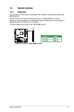
You may install 1GB, 2GB, 4GB, and 8GB unbuffered non-ECC DDR3 DIMMs into the DIMM
sockets.
•
You may install varying memory sizes in Channel A and Channel B. The system maps
the total size of the lower-sized channel for the dual-channel configuration. Any excess
memory from the higher-sized channel is then mapped for single-channel operation.
•
We recommend that you install the memory modules from the blue slots for better
overclocking capability.
•
Always install DIMMs with the same CAS latency. For optimal compatibility, we
recommend that you install memory modules of the same version or date code (D/C)
from the same vendor. Check with the retailer to get the correct memory modules.
•
Due to the memory address limitation on 32-bit Windows
®
OS, when you install 4GB
or more memory on the motherboard, the actual usable memory for the OS can be
about 3GB or less. For effective use of memory, we recommend that you do any of the
following:
-
Install a maximum of 3GB system memory if you are using a 32-bit Windows
®
OS.
-
Use a 64-bit Windows
®
OS if you want to install 4GB or more memory on the
motherboard.
•
This motherboard does not support DIMMs made up of 512Mb (64MB) chips or less.
•
The maximum 32GB memory capacity can be supported with 16GB or above DIMMs.
ASUS will update the memory QVL once the DIMMs are available in the market.
•
The default memory operation frequency is dependent on its Serial Presence Detect
(SPD), which is the standard way of accessing information from a memory module.
Under the default state, some memory modules for overclocking may operate at a
lower frequency than the vendor-marked value. To operate at the vendor-marked
or at a higher frequency, refer to section
2.4 Ai Tweaker menu
for manual memory
frequency adjustment.
•
For system stability, use a more efficient memory cooling system to support a full
memory load (2 DIMMs) or overclocking condition.
Chapter 1: Product introduction
1-12
Summary of Contents for F2A55-M LE
Page 1: ...Motherboard F2A55 M LE ...
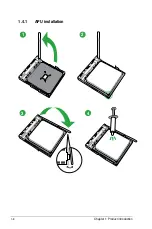
Page 20: ...1 4 1 APU installation 1 4 3 2 Chapter 1 Product introduction 1 8 ...
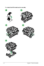
Page 22: ...To uninstall the APU heatsink and fan assembly 5 3 1 4 2 Chapter 1 Product introduction 1 10 ...
Page 29: ...1 5 3 Installing a DIMM 1 2 3 To remove a DIMM B A A ASUS F2A55 M LE 1 17 ...
Page 74: ...2 32 ASUS F2A55 M LE ...

